What is the Difference Between a 6 Pin Terminal Signal Cable and a 6 Pin Power Cable

  When dealing with various types of cables, understanding their specific functions and applications is crucial. Among the many types of cables, 6 pin terminal signal cables and 6 pin power cables are commonly used, but they serve distinct purposes and have different characteristics. Here¨s a detailed look at how these two types of cables differ.If you want to make a big difference in the market, electrical terminal connectors It is necessary to intensify the upgrading of products on the original basis in order to meet the consumption needs of consumers. https://www.xpbdz.com/


  1. Purpose and Function


  6 Pin Terminal Signal Cable:A 6 pin terminal signal cable is designed primarily for the transmission of signals. These signals can be analog or digital, depending on the application. The primary function of this cable is to carry data or control signals between devices. For instance, in industrial automation, these cables connect sensors, controllers, and other equipment to facilitate communication and control processes.


  6 Pin Power Cable:In contrast, a 6 pin power cable is intended to carry electrical power. It is used to connect power sources to devices or components that require electricity to operate. This type of cable is essential in applications where multiple power lines are needed to deliver electricity efficiently to various parts of a system.


  6 PIN terminal signal cable


  2. Wiring and Construction


  6 Pin Terminal Signal Cable:The internal construction of a 6 pin terminal signal cable typically includes multiple insulated conductors. These conductors are arranged to handle different signal paths, which could include data, ground, and power lines if required by the application. The cable may also be shielded to prevent interference and maintain signal integrity.


  6 Pin Power Cable:A 6 pin power cable generally contains thicker conductors compared to signal cables, as it needs to handle higher currents. The insulation material is designed to handle the electrical load and prevent overheating. Power cables are usually not shielded unless there is a need to reduce electromagnetic interference (EMI) for sensitive applications.


  3. Connector Types


  6 Pin Terminal Signal Cable:The connectors used with 6 pin terminal signal cables are often designed to accommodate the specific needs of signal transmission. Common types include Molex, JST, or custom connectors tailored for particular applications. These connectors ensure that the signals are transmitted accurately and reliably.


  6 Pin Power Cable:Power cables often use connectors designed for high-current applications. These connectors are robust and capable of handling significant electrical loads. They may include features such as locking mechanisms to prevent accidental disconnection.


  6 PIN terminal signal cable


  4. Applications


  6 Pin Terminal Signal Cable:These cables are used in applications where precise signal transmission is crucial. Examples include data communication in computers, control systems in industrial machinery, and connection between various electronic devices. They are designed to maintain signal quality and minimize noise.


  6 Pin Power Cable:Power cables are used in applications where reliable power delivery is necessary. They are commonly found in power distribution systems, electrical panels, and devices requiring multiple power inputs. Their design focuses on safety and efficiency in power delivery.


  5. Performance Characteristics


  6 Pin Terminal Signal Cable:Signal cables are designed to offer high performance in terms of signal clarity and low attenuation. The quality of signal transmission is affected by the cable¨s shielding, insulation, and overall construction.


  6 Pin Power Cable:Performance in power cables is measured by their ability to handle current without overheating or causing voltage drops. The gauge of the conductors and the quality of insulation play a crucial role in ensuring safe and efficient power delivery.


  Conclusion


  In summary, the primary difference between a 6 pin terminal signal cable and a 6 pin power cable lies in their intended functions and construction. Signal cables are designed for data transmission with an emphasis on maintaining signal integrity, while power cables are built to deliver electrical power with a focus on handling high currents safely. Understanding these differences helps in selecting the appropriate cable for specific applications, ensuring optimal performance and reliability.
Application of industrial UHF reader

  Industrial UHF reader is widely used in many fields, mainly due to its long-distance reading, group reading, penetration identification and high data transmission rate. The following is a concrete analysis of its application:The industry believes that, rfid module supplier The development of our company marks the rapid and steady progress of the whole industry. https://www.vanchrfid.com/


  I. Logistics warehousing


  Goods tracking and management: In the field of logistics and warehousing, industrial UHF reader can identify and track goods information, and realize the rapid warehousing and warehousing management of goods. This helps to improve storage efficiency, reduce manual operation, shorten the stay time of goods, and reduce personnel management costs. At the same time, it can also improve the confidentiality and safety of goods.


  Inventory: Using the anti-conflict mechanism and batch reading function of UHF reader can greatly save the time of inventory of goods and assets and improve the accuracy and efficiency of inventory management.


  Second, manufacturing


  Material tracking and management: In automatic production, industrial UHF reader can be used for material tracking and management. By sticking RFID tags on materials, materials can be automatically identified and tracked, thus optimizing the functions of production planning and scheduling, material allocation and material traceability, and improving production efficiency and management level.


  Production process monitoring: industrial RFID readers are set at key production nodes, which can record the process information and process operation information of the whole production process and realize the traceability of production. This is helpful to avoid mistakes caused by handwritten and visual information in production environment and improve product quality and safety.


  Industrial RFID reader


  Third, asset management


  Asset inventory and monitoring: With the long-distance reading and penetrating identification function of UHF reader, it is convenient to inventory and monitor all kinds of assets. Both fixed assets and current assets can be identified and tracked quickly and accurately, and the efficiency and accuracy of asset management can be improved.


  IV. Other fields


  Intelligent transportation: In the field of intelligent transportation, such as toll station ETC lane, intelligent parking lot management and other scenes, industrial UHF reader also plays an important role. By quickly identifying RFID tags on vehicles, functions such as fast traffic and automatic fare deduction can be realized, and traffic management efficiency can be improved.


  Retail and payment: In the retail field, UHF reader can be used to realize unmanned retail and fast payment. Consumers only need to carry goods or payment cards with RFID tags through the reader area to complete the purchase and payment process.


  V. Technical characteristics


  Working frequency band: industrial UHF reader generally works in the frequency band of 840-960MHz (there are different standards in different regions of the world), with long reading distance and high data transmission rate.


  Recognition ability: support multi-tag reading and long recognition distance, and can read RFID electronic tags in batches at a time to improve recognition efficiency.


  Penetration recognition: it has the function of penetration recognition, and can still be recognized behind paper, wood, cloth, nonmetal and other materials.


  To sum up, industrial UHF reader has a wide application prospect and important practical value in many fields such as logistics warehousing, manufacturing, asset management and so on. With the continuous development of science and technology and the expansion of application scenarios, its market prospect will be broader.

What Is PSTN Alarm System

  A PSTN (Public Switched Telephone Network) alarm system is a security solution that uses traditional landline telephone networks to transmit alarm signals to a monitoring center. This type of system has been widely used in residential and commercial security due to its reliability and widespread infrastructure.However, in other words, we should know more about it. wired PIR motion sensor The law of development has brought new vitality to the whole industry and revitalized the market. https://www.sunlit-tech.com


  How PSTN Alarm Systems Work


  A PSTN alarm system is connected to a telephone line. When an alarm is triggered, the system sends a signal through the telephone line to a monitoring center or directly to a user¨s phone. This signal alerts the designated parties of a potential security breach, enabling a quick response.


  GSM PSTN Alarm System


  Combining the reliability of PSTN with the flexibility of GSM (Global System for Mobile Communications), a GSM PSTN alarm system enhances security by providing multiple communication channels. This hybrid system uses both a traditional telephone line and a GSM network to ensure alarm signals are always transmitted, even if one network fails.


  Advantages of GSM PSTN Alarm Systems


  Redundancy: The dual network system ensures that alarm signals are transmitted even if one network is down.


  Remote Access: GSM integration allows users to control and monitor the alarm system remotely via mobile phones.


  Flexibility: Suitable for areas without reliable landline service as the GSM component can handle communication.


  Choosing the Right Alarm System


  When selecting between a PSTN alarm system and a PSTN GSM alarm system, consider the following factors:


  Reliability: Traditional PSTN systems are highly reliable but can be compromised if the telephone line is cut.


  Coverage: GSM systems provide better coverage in areas without reliable landline access.


  Cost: PSTN systems are generally less expensive, but GSM systems offer more features and flexibility.


  Features: GSM systems often come with advanced features like remote monitoring, control, and notifications.


  Conclusion:


  PSTN alarm systems offer reliable security through established landline networks, while GSM PSTN alarm systems provide enhanced flexibility and redundancy by combining traditional and mobile communication methods. Depending on your security needs and location, either system could be an effective solution to ensure safety and peace of mind.

What are the water treatment plants in electronic semiconductors

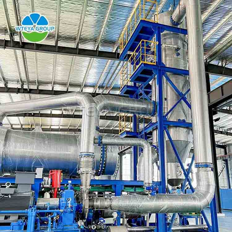
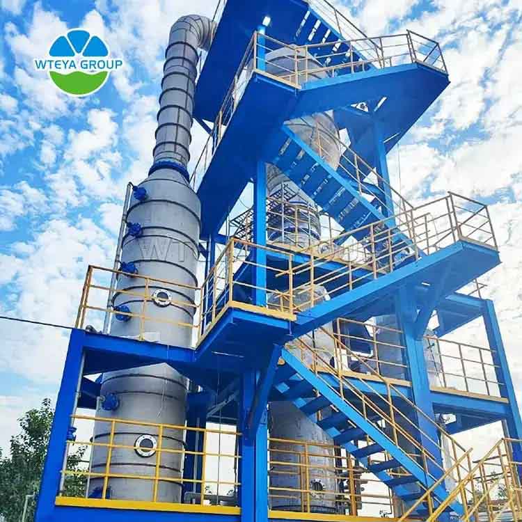
  The production process of electronic semiconductor products has high requirements for water quality. The manufacture of semiconductor materials involves precise chemical reactions and physical processes. Impurities, ions, microorganisms, etc. in the water may cause pollution to the products and affect the performance, stability and reliability of the products. Therefore, water treatment equipment is needed to remove various impurities in the water to ensure the purity of production water.Even if there are obstacles to moving forward, evaporator manufacturer We should also persevere, forge ahead bravely, cut waves in the sea of the market, hang on to Yun Fan and strive for the first place. https://www.wteya.com/


  For example, in the electronic semiconductor industry, WTEYA ultrapure water equipment effectively removes various impurities, ions and microorganisms in the water through a series of high-precision and high-tech treatment processes such as preliminary adsorption filtration, reverse osmosis purification and resin ion exchange, ensuring the production of ultrapure water with extremely high resistivity. This ultrapure water is widely used in key process links such as cleaning, etching, film making and doping in semiconductor manufacturing, and is a key factor in ensuring the performance and quality of semiconductor products.


  Filter


  What water treatment plant is used in the electronic semiconductor industry?


  1. Multi-media/activated carbon filtration system:


  Multi-media filters are usually used as the initial stage of water treatment. Through the combination of different media, they can effectively remove impurities such as suspended matter, colloids, and particles in the water, providing a relatively clean water source for subsequent treatment processes.


  Activated carbon filters are mainly used to remove organic matter, odor, pigments and other impurities in water. Activated carbon has a strong adsorption capacity and can adsorb and remove these pollutants in the water, thereby further improving the purity of the water quality.


  2. Ultrafiltration system:


  First, in the cleaning process, the ultrafiltration membrane can effectively remove particles and ions in the water as a pretreatment process for high-quality ultrapure water systems. This ultrapure water is used to clean semiconductor devices and equipment to ensure the cleanliness of the product surface and avoid the impact of pollutants on product performance and reliability.


  Secondly, ultrafiltration technology is also commonly used in the preparation of process liquids. In the semiconductor manufacturing process, various process liquids are required, such as acids, alkalis, organic solvents, etc. WTEYA ultrafiltration membranes can filter and purify these liquids, remove impurities and particles, and ensure that the purity and quality of the liquids meet production requirements.


  In addition, ultrafiltration technology also plays an important role in the cooling water circulation of the equipment. Semiconductor manufacturing equipment generates a lot of heat during operation, and cooling water is required for heat dissipation. Ultrafiltration membranes can remove particles and ions in cooling water, prevent impurities from damaging the equipment, and ensure the normal operation of the equipment and the stability of the product.


  3. Reverse osmosis membrane system:


  Reverse osmosis membranes are mainly used in the process steps of ultrapure water preparation in the semiconductor industry. In the process of electronic semiconductor manufacturing, ultrapure water is widely used to clean key components such as silicon wafers and chips, which can effectively remove surface particles and organic matter and reduce product defect rates. Reverse osmosis membranes can provide stable, low-tension deionized water to meet the high requirements of the semiconductor industry for water quality.


  In addition, reverse osmosis membrane technology can also provide high-quality cleaning water to ensure the reliability and stability of components. By utilizing the characteristics of reverse osmosis membranes, precise control of water quality can be achieved to meet the strict requirements for ultrapure water in the process of electronic semiconductor manufacturing.

How to Choose the Right Terminal Connection Cable for Your Needs

  Selecting the right terminal connection cable is crucial for ensuring the efficiency and safety of your electrical systems. Whether you are working on a complex industrial project or a simple home wiring job, the choice of cable can significantly impact the performance and reliability of your connections. In this guide, we will explore the key factors to consider when choosing terminal connection cables, the different types available, and practical tips to make an informed decision.In the long run, D-SUB connector The value will be higher and higher, and there will be a great leap in essence. https://www.xpbdz.com/


  Understanding Terminal Connection Cables


  Terminal connection cables are designed to connect electrical circuits and devices securely. They are used in various applications, including industrial machinery, automotive wiring, and household electrical systems. These cables are essential for transmitting power and signals with minimal loss and interference.


  MINI DIN8P connection to XH2.5-5P terminal connection cable


  Key Factors to Consider


  Application Requirements


  Voltage and Current Ratings: Ensure the cable can handle the voltage and current levels required by your application. Using a cable with insufficient ratings can lead to overheating and potential failure.


  Environmental Conditions: Consider the environment where the cable will be installed. Factors such as temperature, humidity, and exposure to chemicals or UV radiation can affect the cable’s performance and lifespan.


  Flexibility and Durability: Depending on your application, you may need a cable that is highly flexible or one that can withstand mechanical stress. Choose a cable with the appropriate flexibility and durability for your needs.


  Cable Specifications


  Conductor Material: The most common conductor materials are copper and aluminum. Copper offers excellent conductivity and flexibility, while aluminum is lighter and more cost-effective. Select the material that best suits your application requirements.


  Insulation Type: The insulation protects the conductor from external factors and prevents short circuits. Common insulation materials include PVC, rubber, and silicone. Choose an insulation type that matches your environmental conditions and application needs.


  Shielding: Shielded cables are used to reduce electromagnetic interference (EMI) and ensure signal integrity. If your application is sensitive to EMI, consider using shielded cables.


  Standards and Certifications


  Ensure that the terminal connection cable complies with relevant industry standards and certifications. This guarantees that the cable meets safety and performance requirements. Look for certifications such as UL, CE, and ISO.


  MINI DIN8P connection to XH2.5-5P terminal connection cable


  Types of Terminal Connection Cables


  1.Single-Core Cables


  Single-core cables consist of a single conductor covered with insulation. They are used in applications where flexibility is not a primary concern, such as fixed installations in buildings.


  2.Multi-Core Cables


  Multi-core cables contain multiple conductors within a single sheath. They are ideal for applications requiring multiple connections in a compact form, such as control panels and automotive wiring.


  3.Coaxial Cables


  Coaxial cables have a central conductor surrounded by insulation, a metallic shield, and an outer insulating layer. They are used for transmitting high-frequency signals with minimal interference, such as in television and internet connections.


  4.Twisted Pair Cables


  Twisted pair cables consist of pairs of conductors twisted together to reduce EMI. They are commonly used in telecommunications and networking applications.


  Practical Tips for Choosing the Right Cable


  Assess Your Needs: Start by identifying the specific requirements of your application, including electrical load, environmental conditions, and physical constraints.


  Consult Technical Data: Refer to the technical specifications and datasheets provided by cable manufacturers. These documents offer detailed information about the cable’s performance characteristics and suitability for different applications.


  Seek Expert Advice: If you are unsure about the best cable for your needs, consult with an electrical engineer or a knowledgeable supplier. They can provide valuable insights and recommendations based on their expertise.


  Consider Future Needs: When choosing a cable, consider any potential future requirements. Selecting a cable with higher ratings or additional features can save you from having to upgrade later.


  Conclusion


  Choosing the right terminal connection cable is essential for the success of your electrical projects. By considering factors such as application requirements, cable specifications, and industry standards, you can make an informed decision that ensures optimal performance and safety. Whether you are working on a small DIY project or a large-scale industrial installation, selecting the appropriate terminal connection cable will help you achieve reliable and efficient electrical connections.

What are the advantages and disadvantages of high-frequency split reade

  The split reader can connect multiple reader antennas at the same time, which is flexible in deployment and wide in reading distance, and has applications in many scenes. Let’s take a look at the advantages and disadvantages of high-frequency split reader.in fact rfid module supplier Our related products were once praised by users, which is the best self-affirmation of the products. https://www.vanchrfid.com/


  Advantages of high frequency split reader


  1, high flexibility


  The read-write module and antenna of high-frequency split reader are separated from each other, and the antenna can be installed and used independently, allowing the position and angle of the antenna to be adjusted to flexibly adapt to different application environments and requirements. This design is especially suitable for high altitude, underground parking and other complex environments, ensuring that the reader can effectively read and write RFID tags.


  2. Wide reading range


  The split reader can easily expand the coverage of the reader and improve the reading and writing efficiency by increasing the number of antennas or adjusting the antenna layout to meet the ever-changing application requirements.


  3, the maintenance cost is low


  The read-write module of the high-frequency split reader is deployed and used separately from the antenna. Once the antenna fails, the equipment can be easily replaced, and the maintenance cost is relatively low.


  Disadvantages of high frequency split reader


  1, the installation is more complicated.


  Split reader needs to design the installation position of antenna and reader according to the application scenario. If a reader is connected with multiple antennas at the same time, it needs to adjust the deployment and installation, and the installation steps are relatively complicated.


  2, vulnerable to environmental interference


  There is a certain distance between the reader and the antenna, and it will be more easily disturbed by external factors under harsh environmental conditions such as metal and moisture, which will affect the recognition effect.


  ANDEAWELL UHF split reader RU5321M&T-S04 can be connected with four antennas to work at the same time, which is convenient for distributed installation and deployment of antennas. The reading distance can reach 0~5000mm (the farthest distance is related to the label size), and the protection level is IP67. It is suitable for all kinds of harsh environments in the industrial field; Built-in filter and isolation module has strong anti-interference ability, high receiving sensitivity, stable performance and strong reliability. It supports standard industrial communication protocol ModBus and is convenient for users to integrate into control systems such as PLC.


  At present, high-frequency RFID split readers are widely used in warehousing logistics, book management, production line automation and other fields. Antennas and readers are installed at multiple entrances and exits or shelves of warehouses to realize the rapid entry and exit of goods and inventory checking, and improve the efficiency of warehousing management. The reader and antenna are installed on the intelligent bookshelf to realize the rapid positioning and inventory of books and improve the efficiency of book management; The reader and antenna are installed at the key nodes of the production line to realize the automatic monitoring and traceability of the production process.

Brief Introduction of PIR Sensor

  From some points of view, wired PIR motion sensor It is the core driving force to better promote the rapid development of the surrounding markets. https://www.sunlit-tech.com

  PIR sensor (Passive Infrared Sensor) is a passive infrared sensor. It is widely used in consumer products such as doorbells, cat eyes, induction switches, night lights, and security because of its low power consumption, low price, and simple use.


  (1) PIR detection principle


  PIR also has another alias, which is pyroelectric infrared sensor. Its detection principle is the pyroelectric effect, that is, the phenomenon that a substance will generate electric charge when the temperature changes. The normal human body temperature is 36-37 degrees, and the infrared radiation released is about 9-10um. The detection wavelength range of pir motion detector is generally in the range of 5-14um. That is, within the detection range of PIR, if there is an energy change of 5-14um wavelength, the PIR sensor will generate a current change, thereby giving a trigger signal. It should be noted here that PIR detects energy changes, not infrared radiation of a fixed wavelength. If an object with a fixed wavelength is not moving, PIR will not detect it.


  (2) Advantages of PIR


  Low power consumption, typical power consumption is about 10uA


  Low price, ranging from one or two yuan to five or six yuan


  Easy to use, the simplest one only needs to detect a pin level signal


  (3) PIR classification


  There are many types of PIR motion detector, which can be roughly divided into the following ways:


  Enablement controllable: switchable PIR


  Output signal type: digital PIR and analog PIR


  Is the sensitivity adjustable: adjustable PIR and non-adjustable PIR


  Sensitivity adjustment method: hardware adjustment and software programming adjustment PIR


  (4) PIR selection


  When selecting a PIR sensor, we generally need to consider the following basic requirements: voltage range, operating current, number of pins required, data output format, whether the sensitivity is adjustable, structural package size, and compatibility with the Fresnel lens. Another important consideration is cost. Without considering cost, it doesn¨t matter whether you choose a model or not. Just choose the best one. In actual product development, especially for consumer products, prices are very sensitive. Basically, all bosses want to use the cheapest device and debug it to achieve the best effect, especially for products with large shipments. If you don¨t have high requirements for product quality, it doesn¨t matter. If you have strict requirements for product quality and performance, you need to be very careful when selecting a model to avoid replacing the device when you find that it does not meet the requirements in the later stages of the project.

Seawater desalination reverse osmosis water treatment system

  The main task of seawater desalination is to remove salt and other impurities from seawater to make it drinkable or industrial water. In this process, in addition to producing desalinated water, a large amount of concentrated brine is also generated. These concentrated brine contains high concentrations of salt and possible chemical treatment agents. If they are directly discharged into the ocean or underground, they may have a negative impact on the environment.In addition to domestic, evaporator It has also emerged in the international field and gradually gained the favor of more foreign friends. https://www.wteya.com/


  Introduction to seawater desalination reverse osmosis water treatment system


  The seawater desalination reverse osmosis water treatment system is a high-efficiency water treatment method specifically used to treat concentrated brine produced during seawater desalination. Through advanced reverse osmosis technology, the system can further recycle and utilize this part of water resources while reducing the impact on the environment.


  Composition of seawater desalination reverse osmosis water treatment system


  The seawater desalination reverse osmosis water treatment system is mainly composed of high-pressure pumps, reverse osmosis membrane elements, energy recovery devices and control systems. The high-pressure pump is responsible for providing sufficient pressure for water molecules to reverse osmosis; the reverse osmosis membrane is the core of the work, which only allows water molecules to pass through and intercepts salt and other impurities; the energy recovery device is used to recover energy in the system to improve efficiency; the control system ensures the stable operation of the entire system.


  Principle of seawater desalination reverse osmosis water treatment technology


  The working principle of seawater desalination reverse osmosis water treatment system is based on the selective permeability of semipermeable membrane, that is, under pressure, water molecules can penetrate from the high-salinity side to the low-salinity side. By applying a pressure higher than the osmotic pressure, water molecules are reversed through the semipermeable membrane, thereby achieving the purpose of removing soluble salts and other impurities.


  Advantages of seawater desalination reverse osmosis water treatment system


  The advantages of seawater desalination reverse osmosis water treatment system include low energy consumption, high treatment efficiency and environmental friendliness. It can effectively further extract fresh water from concentrated brine and improve the overall water utilization rate. In addition, the water quality treated by reverse osmosis can reach a higher standard and is suitable for a variety of uses.


  WTEYA water treatment plant manufacturer, focusing on the research and development and production of seawater desalination reverse osmosis water treatment system, has more than fifteen years of environmental protection experience, and is committed to providing a full set of water treatment equipment and solutions for various industries. Our seawater desalination reverse osmosis water treatment system can not only effectively treat concentrated brine, but also optimize the utilization of water resources and help achieve sustainable development goals.

How Wet Press Mould Pulp Supports Circular Economy Principles?

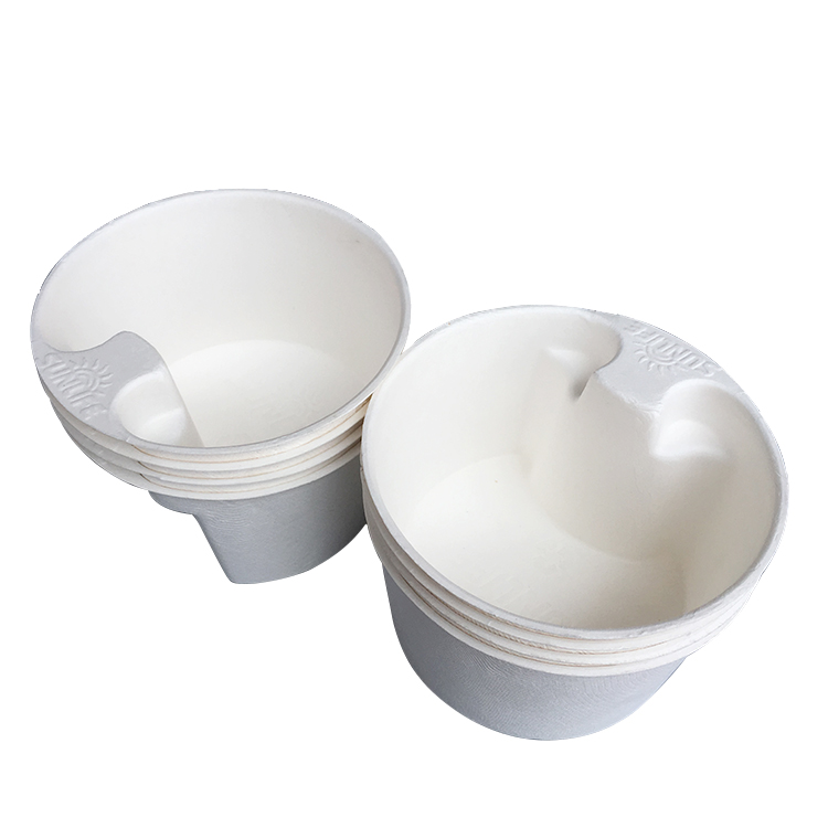
  Wet press molded pulp, also known as wet pressing molded pulp, is a sustainable and eco-friendly material that supports circular economy principles. This innovative material is used to create molded pulp packaging, such as trays and containers, which are increasingly being adopted by businesses looking for environmentally friendly packaging solutions.As it happens, many people are killed molded pulp packaging And bring more benefits, make it flourish, and promote the industry greatly. https://www.pulptray.com/


  Circular economy principles aim to minimize waste and maximize the use of resources by promoting the reuse, recycling, and regeneration of materials. Wet press molded pulp is a prime example of how these principles can be put into practice in the packaging industry.One of the key advantages of wet press molded pulp is its raw material source. It is predominantly made from recycled paper and cardboard, which reduces the demand for virgin materials and diverts waste from landfills. By using recycled materials as its primary source, wet press molded pulp supports the circular economy by closing the loop on paper and cardboard waste.


  Furthermore, the production process of wet press molded pulp packaging aligns with circular economy principles. The manufacturing process starts with the collection of used paper and cardboard, which is then processed into a pulp. This pulp is mixed with water and formed into shape using molds. After shaping, the wet pulp is subjected to a pressing process to remove excess water, resulting in a sturdy and durable packaging material.The versatility of wet press molded pulp allows it to be used for various packaging applications, from food and beverage trays to protective cushioning for electronic devices. This flexibility contributes to the circular economy by extending the lifespan of recycled materials and reducing the need for single-use plastics and other non-biodegradable packaging materials.


  molded pulp packaging


  biodegradable pulp packaging


  recycled pulp packaging


  In addition to its sustainable sourcing and production process, wet press molded pulp packaging is also fully recyclable and biodegradable. This means that at the end of its useful life, the packaging can be recycled to make new molded pulp products or composted to return nutrients to the soil. By ensuring that the end-of-life options for packaging align with circular economy principles, wet press molded pulp closes the loop on its own lifecycle and minimizes its environmental impact.The adoption of wet press molded pulp packaging by businesses further promotes circular economy principles by encouraging a shift towards a more sustainable and resource-efficient approach to packaging. As more companies choose eco-friendly packaging solutions, the demand for wet press molded pulp products increases, creating a market for recycled materials and driving investment in sustainable packaging technologies.


  Overall, wet press molded pulp supports circular economy principles by utilizing recycled materials, minimizing waste, and offering fully recyclable and biodegradable packaging solutions. Its adoption by businesses contributes to the transition towards a more sustainable and circular approach to packaging, demonstrating the potential for innovative materials to drive positive change in the industry.

What are the configuration and use steps of UHF split reader

  UHF split reader can connect multiple antennas at the same time and be installed in different areas to read and write RFID tags. It is also often used in large-scale intensive reading scenes such as warehousing and shelves. The configuration and use of UHF split reader involves many steps. The following is a general guide.Therefore, we should understand rfid tag Many benefits, absorb and summarize, and use them. https://www.vanchrfid.com/


  First, the preparation stage


  Determine the position and support:


  Determine the installation position of UHF split reader and select the appropriate bracket type to ensure the stable installation and maximum function of the equipment.


  Check equipment integrity:


  Check whether the reader body, antenna, cable, power supply and other accessories are complete and intact.


  Prepare necessary tools:


  Prepare screwdriver, cable tie, network cable and other tools needed for installation and connection.


  Second, the installation and connection


  Install the reader:


  Fix the reader in the selected position and fix it with screws or tie straps.


  Connect antenna:


  Connect the antenna with the antenna interface of the reader to ensure that the connection is firm and not loose.


  Connect the power supply:


  Connect the reader to the power socket with the provided power cord to ensure that the voltage and current meet the equipment requirements.


  Network connection:


  If the reader supports network connection (such as Ethernet, Wi-Fi, etc.), configure the network according to the equipment manual to ensure that the reader can access the network.


  Third, the configuration software


  Install configuration software:


  Install the necessary configuration software according to the equipment manual or the information provided by the supplier. For example, for Siemens PLC configuration, Broadcom software may be required.


  Add device:


  Create a new project in the configuration software, and add UHF split reader as a new device. Input device parameters such as IP address and port number according to the software prompts.


  Configuration parameters:


  Configure various parameters of the reader, such as reading frequency, reading range, data format, etc. The setting of these parameters will directly affect the performance and stability of the reader.


  Testing and debugging:


  After the configuration is completed, the reader is tested with the test tag to check whether it can read and write data normally. Make necessary debugging and optimization according to the test results.


  IV. Use and Maintenance


  Daily use:


  In daily use, operate according to the equipment manual or operation manual to ensure the correct use of the reader.


  Data management:


  Manage and analyze the data collected by the reader to meet the business needs.


  Regular maintenance:


  Regularly clean and check the reader to ensure that it is in good working condition. Pay attention to check the antenna connection and cable wear, and replace the damaged parts in time.


  Software update:


  Pay attention to the software update information released by equipment suppliers, and update the configuration software and firmware versions in time to improve the performance and security of equipment.


  V. Matters needing attention


  Safe operation:


  In the process of installation, configuration and use, strictly abide by the safety operation rules to prevent electric shock, short circuit and other safety accidents.


  Electromagnetic interference:


  Pay attention to the interference between the reader and the surrounding electromagnetic equipment and avoid placing the reader in a strong electromagnetic field environment.


  Label compatibility:


  Confirm the compatibility of the selected tag with the reader before use to ensure the correct reading and writing of data.


  Technical support:


  In case of technical problems, contact equipment suppliers or professional technicians for help in time.


  Through the above steps, users can complete the configuration and use process of UHF split reader. However, the specific steps may vary depending on the equipment model and supplier, so you should refer to the equipment manual or the detailed information provided by the supplier in actual operation.