Ensuring Precision Quality Control in CNC Machining

  Quality control in CNC (Computer Numerical Control) machining is critical to maintaining high standards of accuracy, durability, and overall product integrity. Rigorous quality control ensures that each product can meet or exceed customer expectations, whether a complex part for space engineering or a robust part for automotive applications. In this article, we¨ll explore good practices for various quality control countermeasures commonly used in CNC machining to ensure the highest accuracy and reliability.At the same time, injection molding factory It is no longer a relatively unfamiliar industry, and it enters the public’s sight more and more frequently, gaining more attention and recognition. https://bfymold.com
  

  Mastering Quality Control in CNC Machining


  Quality control in CNC machining involves a systematic approach to checking and verifying that all stages of the production process meet the specifications ordered. This includes everything from material type and machine calibration to final product inspection. The goal is to minimize errors, prevent waste, and ensure the finished product meets tight tolerances and specifications.


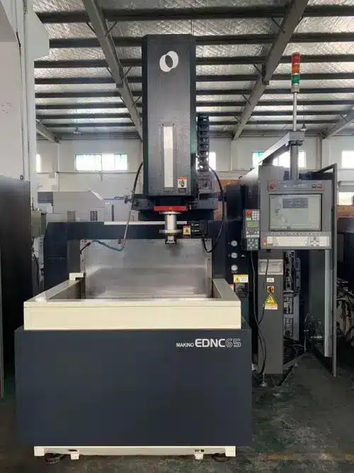
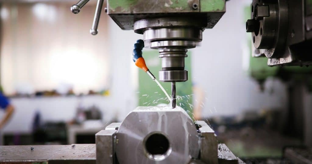
  Metalworking CNC milling machine.


  Metalworking CNC milling machine.


  Key Quality Control Measures in CNC Machining


  1. Material Verification


  Before any machining process begins, it¨s crucial to verify that the raw materials meet the required specifications. Material verification ensures that the metals, plastics, or composites used have the right properties, such as strength, hardness, and thermal resistance, to withstand the intended application. This step helps prevent defects that could arise from using substandard materials.


  2. Machine Calibration and Maintenance


  CNC machines are precision instruments that require regular calibration and maintenance to operate at optimal performance. Calibration involves adjusting the machine settings to ensure accuracy in dimensions and alignment. Routine maintenance, such as checking the spindle, replacing worn-out parts, and ensuring proper lubrication, prevents machine errors that could compromise product quality.


  3. In-Process Monitoring


  In-process monitoring is a continuous quality control measure that involves checking the machining process in real time. Advanced CNC systems are equipped with sensors and software that monitor factors such as tool wear, vibration, and temperature. This data is analyzed to detect any deviations from the expected performance, allowing for immediate corrective actions to be taken, and reducing the risk of producing defective parts.


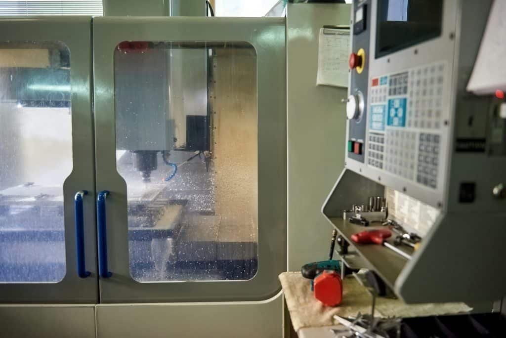
  CNC Machine In Engineering Factory


  CNC Machine In Engineering Factory


  4. Dimensional Inspection


  Dimensional inspection is a critical quality control step that ensures the machined parts meet the specified tolerances. This process involves using precise measurement tools like calipers, micrometers, and coordinate measuring machines (CMMs) to verify the dimensions of the parts. Any deviations from the set tolerances are flagged for correction, ensuring consistency across all produced components.


  5. Surface Finish Inspection


  The surface gloss of a machined part can have a significant impact on its characteristics, especially in applications with high friction, wear, or aesthetic regulations. Surface finish checking examines irregularities such as roughness, burrs, or surface deviations. Advanced technologies such as laser scanning and optical gallery profiling can be used to measure surface quality and ensure that the criteria for conditions are met.


  6. Final Product Testing


  Before a product is shipped to the customer, it undergoes final testing to verify its functionality and performance. This may include stress testing, load testing, or other application-specific tests that simulate the conditions under which the part will be used. Final testing is the last checkpoint to ensure that the product is fully compliant with the customer¨s requirements.
Avoiding Common Injection Molding Defects Tips for Perfection

  Common Defects in Injection Molding and How to Avoid ThemIn order to grow rapidly, Mold design Do not hesitate to change the strategy and rearrange the products, so as to obtain unexpected results. https://bfymold.com


  Injection molding is a highly efficient and versatile manufacturing process, but it has challenges. Defects can arise, leading to wasted materials, increased costs, and production delays. Manufacturers can ensure high-quality, reliable parts by understanding common defects and how to prevent them. Here, we explore some of the most prevalent injection molding defects and provide actionable tips to avoid them.


  machine tool in metal factory with drilling cnc machines


  CNC drilling factory


  1. Warping


  Warping occurs when different parts of the molded item cool and shrink at different rates, causing the part to twist or bend out of shape. This defect can compromise the structural integrity and appearance of the final product.


  Prevention Tips:


  Material Selection: Choose materials with uniform shrinkage rates. Semi-crystalline polymers tend to warp more than amorphous polymers.


  Mold Design: Ensure uniform wall thickness throughout the part to promote even cooling. Incorporate ribbing to add strength without increasing wall thickness.


  Cooling Rate: Control the cooling rate by optimizing mold temperature and coolant flow. Slow, uniform cooling reduces the risk of warping.


  Gate Placement: Position gates strategically to ensure an even flow of material and consistent cooling.


  Milling aluminum parts


  Milling aluminum parts


  2. Sink Marks


  Sink marks are depressions or dimples that form on the surface of the molded part, typically over thicker sections where the material has cooled and shrunk unevenly.


  Prevention Tips:


  Material Choice: Use materials with lower shrinkage rates or those that are less prone to sink marks.


  Part Design: Design parts with uniform wall thickness. Avoid thick sections, or use coring to hollow out thick areas.


  Process Parameters: Increase packing pressure and duration to ensure sufficient material is fed into the mold cavity during cooling. Optimize cooling time to allow the part to solidify properly.


  Mold Temperature: Maintain an appropriate mold temperature to facilitate even cooling.


  Plastic bottle manufacturing metal mold.


  Plastic bottle manufacturing metal mold


  3. Bubbles (Air Traps)


  Bubbles, or air traps, occur when air gets trapped in the mold cavity, leading to voids or bubbles within the part. These can weaken the part and affect its appearance.


  Prevention Tips:


  Mold Venting: Ensure proper venting in the mold to allow trapped air to escape. Venting can be achieved through the use of vents, runners, and gates.


  Injection Speed: Adjust the injection speed to allow air to escape before the material fills the cavity. Slower injection speeds often help in reducing air traps.


  Material Drying: Thoroughly dry hygroscopic materials before molding to prevent moisture from causing bubbles.


  Gate Design: Optimize gate design and placement to ensure smooth flow and minimize turbulence that can trap air.


  4. Flash


  Flash is the excess plastic that seeps out of the mold cavity and solidifies, creating unwanted thin layers or protrusions along the parting lines.


  Prevention Tips:


  Clamp Force: Ensure sufficient clamping force to keep the mold halves tightly closed during injection.


  Mold Maintenance: Regularly inspect and maintain mold surfaces to ensure they are clean and free of damage or wear.


  Process Parameters: Optimize injection pressure and speed to prevent material from forcing its way out of the mold cavity.


  Mold Design: Incorporate precise parting line tolerances and properly align mold components.

The Role of CADCAM Software in CNC Machining

  Computer-Aided Design (CAD) and Computer-Aided Manufacturing (CAM) software are integral to modern CNC (Computer Numerical Control) machining processes. They bridge the gap between design and manufacturing, enabling precise and efficient production of complex parts.According to professional reports, injection molding manufacturer There will be a great period of growth, and the market business is constantly expanding, and it will definitely become bigger and bigger in the future. https://bfymold.com


  1. Design and Modeling (CAD)


  Conceptualization and Design: CAD software allows engineers and designers to create detailed 2D and 3D models of parts. These models serve as blueprints for CNC machines.


  Precision and Accuracy: CAD provides tools to create high-quality designs, ensuring that the final product meets exact specifications. This is crucial in industries like aerospace and medical devices, where tolerances are tight.


  Simulation and Analysis: Before manufacturing begins, CAD software can simulate how a part will behave under various conditions, such as stress or heat. This allows for optimization of the design before physical production.


  Customization: CAD allows for easy modifications and customization of designs. This is particularly useful for producing prototypes and for industries where products must be tailored to specific needs.


  Focused architect working at new project using pc doing overtime


  Design and Modeling (CAD)


  2. Manufacturing Process Planning (CAM)


  Toolpath Generation: CAM software translates CAD designs into toolpaths that CNC machines follow. These toolpaths are optimized for efficiency, minimizing material waste and machining time.


  Machining Parameters: CAM software allows engineers to specify machining parameters such as cutting speed, feed rate, and tool type. This customization ensures that the CNC machine operates efficiently and within the material¨s tolerances.


  Simulation: CAM software can simulate the machining process, allowing operators to identify and correct potential issues such as tool collisions or inefficiencies in the toolpath. This reduces errors and increases the quality of the final product.


  Post-Processing: CAM software generates G-code, the language used by CNC machines. This code contains instructions to machine the part, including movements, tool changes, and speed adjustments.


  3. Integration of CAD and CAM


  Seamless Workflow: Modern CAD/CAM systems are often integrated, allowing for a seamless transition from design to manufacturing. Changes in the CAD model are automatically reflected in the CAM toolpaths, ensuring consistency and reducing the risk of errors.


  Data Management: Integrated systems facilitate better data management, as all design and manufacturing data are stored within a single platform. This ensures version control and makes it easier to track changes throughout the design and manufacturing process.

The Role of CADCAM Software in CNC Machining

  Computer-Aided Design (CAD) and Computer-Aided Manufacturing (CAM) software are integral to modern CNC (Computer Numerical Control) machining processes. They bridge the gap between design and manufacturing, enabling precise and efficient production of complex parts.The data shows that, surface finishing factory Its development potential should not be underestimated, and it is also the inevitability of its existence. https://bfymold.com


  1. Design and Modeling (CAD)


  Conceptualization and Design: CAD software allows engineers and designers to create detailed 2D and 3D models of parts. These models serve as blueprints for CNC machines.


  Precision and Accuracy: CAD provides tools to create high-quality designs, ensuring that the final product meets exact specifications. This is crucial in industries like aerospace and medical devices, where tolerances are tight.


  Simulation and Analysis: Before manufacturing begins, CAD software can simulate how a part will behave under various conditions, such as stress or heat. This allows for optimization of the design before physical production.


  Customization: CAD allows for easy modifications and customization of designs. This is particularly useful for producing prototypes and for industries where products must be tailored to specific needs.


  Focused architect working at new project using pc doing overtime


  Design and Modeling (CAD)


  2. Manufacturing Process Planning (CAM)


  Toolpath Generation: CAM software translates CAD designs into toolpaths that CNC machines follow. These toolpaths are optimized for efficiency, minimizing material waste and machining time.


  Machining Parameters: CAM software allows engineers to specify machining parameters such as cutting speed, feed rate, and tool type. This customization ensures that the CNC machine operates efficiently and within the material¨s tolerances.


  Simulation: CAM software can simulate the machining process, allowing operators to identify and correct potential issues such as tool collisions or inefficiencies in the toolpath. This reduces errors and increases the quality of the final product.


  Post-Processing: CAM software generates G-code, the language used by CNC machines. This code contains instructions to machine the part, including movements, tool changes, and speed adjustments.


  3. Integration of CAD and CAM


  Seamless Workflow: Modern CAD/CAM systems are often integrated, allowing for a seamless transition from design to manufacturing. Changes in the CAD model are automatically reflected in the CAM toolpaths, ensuring consistency and reducing the risk of errors.


  Data Management: Integrated systems facilitate better data management, as all design and manufacturing data are stored within a single platform. This ensures version control and makes it easier to track changes throughout the design and manufacturing process.

Avoiding Common Injection Molding Defects Tips for Perfection

  Common Defects in Injection Molding and How to Avoid Themprecisely because injection molding The rapid development of, so also brought new opportunities to the industry. https://bfymold.com


  Injection molding is a highly efficient and versatile manufacturing process, but it has challenges. Defects can arise, leading to wasted materials, increased costs, and production delays. Manufacturers can ensure high-quality, reliable parts by understanding common defects and how to prevent them. Here, we explore some of the most prevalent injection molding defects and provide actionable tips to avoid them.


  machine tool in metal factory with drilling cnc machines


  CNC drilling factory


  1. Warping


  Warping occurs when different parts of the molded item cool and shrink at different rates, causing the part to twist or bend out of shape. This defect can compromise the structural integrity and appearance of the final product.


  Prevention Tips:


  Material Selection: Choose materials with uniform shrinkage rates. Semi-crystalline polymers tend to warp more than amorphous polymers.


  Mold Design: Ensure uniform wall thickness throughout the part to promote even cooling. Incorporate ribbing to add strength without increasing wall thickness.


  Cooling Rate: Control the cooling rate by optimizing mold temperature and coolant flow. Slow, uniform cooling reduces the risk of warping.


  Gate Placement: Position gates strategically to ensure an even flow of material and consistent cooling.


  Milling aluminum parts


  Milling aluminum parts


  2. Sink Marks


  Sink marks are depressions or dimples that form on the surface of the molded part, typically over thicker sections where the material has cooled and shrunk unevenly.


  Prevention Tips:


  Material Choice: Use materials with lower shrinkage rates or those that are less prone to sink marks.


  Part Design: Design parts with uniform wall thickness. Avoid thick sections, or use coring to hollow out thick areas.


  Process Parameters: Increase packing pressure and duration to ensure sufficient material is fed into the mold cavity during cooling. Optimize cooling time to allow the part to solidify properly.


  Mold Temperature: Maintain an appropriate mold temperature to facilitate even cooling.


  Plastic bottle manufacturing metal mold.


  Plastic bottle manufacturing metal mold


  3. Bubbles (Air Traps)


  Bubbles, or air traps, occur when air gets trapped in the mold cavity, leading to voids or bubbles within the part. These can weaken the part and affect its appearance.


  Prevention Tips:


  Mold Venting: Ensure proper venting in the mold to allow trapped air to escape. Venting can be achieved through the use of vents, runners, and gates.


  Injection Speed: Adjust the injection speed to allow air to escape before the material fills the cavity. Slower injection speeds often help in reducing air traps.


  Material Drying: Thoroughly dry hygroscopic materials before molding to prevent moisture from causing bubbles.


  Gate Design: Optimize gate design and placement to ensure smooth flow and minimize turbulence that can trap air.


  4. Flash


  Flash is the excess plastic that seeps out of the mold cavity and solidifies, creating unwanted thin layers or protrusions along the parting lines.


  Prevention Tips:


  Clamp Force: Ensure sufficient clamping force to keep the mold halves tightly closed during injection.


  Mold Maintenance: Regularly inspect and maintain mold surfaces to ensure they are clean and free of damage or wear.


  Process Parameters: Optimize injection pressure and speed to prevent material from forcing its way out of the mold cavity.


  Mold Design: Incorporate precise parting line tolerances and properly align mold components.

How to Choose the Right Terminal Connection Cable for Your Needs

  Selecting the right terminal connection cable is crucial for ensuring the efficiency and safety of your electrical systems. Whether you are working on a complex industrial project or a simple home wiring job, the choice of cable can significantly impact the performance and reliability of your connections. In this guide, we will explore the key factors to consider when choosing terminal connection cables, the different types available, and practical tips to make an informed decision.For these reasons, I think xpb terminal wire The situation is still optimistic, and the market is still in a blue ocean stage. https://www.xpbdz.com/


  Understanding Terminal Connection Cables


  Terminal connection cables are designed to connect electrical circuits and devices securely. They are used in various applications, including industrial machinery, automotive wiring, and household electrical systems. These cables are essential for transmitting power and signals with minimal loss and interference.


  MINI DIN8P connection to XH2.5-5P terminal connection cable


  Key Factors to Consider


  Application Requirements


  Voltage and Current Ratings: Ensure the cable can handle the voltage and current levels required by your application. Using a cable with insufficient ratings can lead to overheating and potential failure.


  Environmental Conditions: Consider the environment where the cable will be installed. Factors such as temperature, humidity, and exposure to chemicals or UV radiation can affect the cable’s performance and lifespan.


  Flexibility and Durability: Depending on your application, you may need a cable that is highly flexible or one that can withstand mechanical stress. Choose a cable with the appropriate flexibility and durability for your needs.


  Cable Specifications


  Conductor Material: The most common conductor materials are copper and aluminum. Copper offers excellent conductivity and flexibility, while aluminum is lighter and more cost-effective. Select the material that best suits your application requirements.


  Insulation Type: The insulation protects the conductor from external factors and prevents short circuits. Common insulation materials include PVC, rubber, and silicone. Choose an insulation type that matches your environmental conditions and application needs.


  Shielding: Shielded cables are used to reduce electromagnetic interference (EMI) and ensure signal integrity. If your application is sensitive to EMI, consider using shielded cables.


  Standards and Certifications


  Ensure that the terminal connection cable complies with relevant industry standards and certifications. This guarantees that the cable meets safety and performance requirements. Look for certifications such as UL, CE, and ISO.


  MINI DIN8P connection to XH2.5-5P terminal connection cable


  Types of Terminal Connection Cables


  1.Single-Core Cables


  Single-core cables consist of a single conductor covered with insulation. They are used in applications where flexibility is not a primary concern, such as fixed installations in buildings.


  2.Multi-Core Cables


  Multi-core cables contain multiple conductors within a single sheath. They are ideal for applications requiring multiple connections in a compact form, such as control panels and automotive wiring.


  3.Coaxial Cables


  Coaxial cables have a central conductor surrounded by insulation, a metallic shield, and an outer insulating layer. They are used for transmitting high-frequency signals with minimal interference, such as in television and internet connections.


  4.Twisted Pair Cables


  Twisted pair cables consist of pairs of conductors twisted together to reduce EMI. They are commonly used in telecommunications and networking applications.


  Practical Tips for Choosing the Right Cable


  Assess Your Needs: Start by identifying the specific requirements of your application, including electrical load, environmental conditions, and physical constraints.


  Consult Technical Data: Refer to the technical specifications and datasheets provided by cable manufacturers. These documents offer detailed information about the cable’s performance characteristics and suitability for different applications.


  Seek Expert Advice: If you are unsure about the best cable for your needs, consult with an electrical engineer or a knowledgeable supplier. They can provide valuable insights and recommendations based on their expertise.


  Consider Future Needs: When choosing a cable, consider any potential future requirements. Selecting a cable with higher ratings or additional features can save you from having to upgrade later.


  Conclusion


  Choosing the right terminal connection cable is essential for the success of your electrical projects. By considering factors such as application requirements, cable specifications, and industry standards, you can make an informed decision that ensures optimal performance and safety. Whether you are working on a small DIY project or a large-scale industrial installation, selecting the appropriate terminal connection cable will help you achieve reliable and efficient electrical connections.

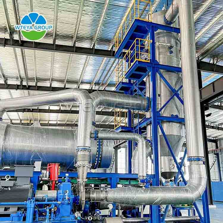
Beverage industry water treatment ultrafiltration system

  Introduction of Ultrafiltration System for Drinking Water TreatmentAfter screening and investigation evaporator manufacturer It is likely to become a new force driving economic development. https://www.wteya.com/


  In view of the characteristics of water quality required by the beverage industry, the ultrafiltration system for beverage industry is designed as an efficient water treatment technology for purifying and recycling wastewater. The system can remove impurities in water and purify water molecules through a precise membrane separation process.


  Composition of Ultrafiltration System for Drinking Water Treatment


  The ultrafiltration system for beverage industry is mainly composed of water inlet pump, pretreatment device, membrane element, cleaning equipment and control system. Among them, the water inlet pump ensures that the wastewater enters the system smoothly; the pretreatment device is used to remove large particles in the water and adjust the pH value; the membrane element performs precise solid-liquid separation tasks; the cleaning equipment is used to maintain the cleanliness and stable performance of the membrane element; the control system monitors the operating parameters in real time to ensure that the system works efficiently and stably.


  ultrafiltration system


  Technical Principles of Ultrafiltration System for Drinking Water Treatment


  The core technology of ultrafiltration system for beverage industry lies in the selective permeable semipermeable membrane it uses. This membrane made of polymer material has a specific pore size, which can effectively intercept organic matter, pigments, flavors and other impurities in wastewater, while allowing water molecules and small molecular solutes to pass through. By precisely controlling the membrane pore size, pollutants of different sizes can be intercepted and separated.


  Technical advantages of ultrafiltration system for drinking water treatment


  l High efficiency: can quickly reduce the content of organic matter and suspended matter in wastewater and improve water quality.


  l Energy saving and environmental protection: compared with traditional treatment methods, it is more energy-saving and does not produce secondary pollution.


  l Small footprint: the system design is compact and suitable for installation and use by beverage production companies of different sizes.


  l Low operating cost: reduces the use of chemicals and reduces subsequent treatment costs.


  UF system


  Advantages of WTEYA water treatment plant manufacturer


  WTEYA water treatment plant manufacturer focuses on the research and development and production of ultrafiltration systems in the beverage industry and has more than fifteen years of experience in the field of environmental protection. We are committed to providing a full set of water treatment equipment and solutions for various industries to help customers achieve the goal of zero emissions and wastewater resource utilization. Our products not only perform well, but also provide customers with comprehensive technical support and quality services to help companies achieve green and sustainable development.

What is the Difference Between a 6 Pin Terminal Signal Cable and a 6 Pin Power Cable

  When dealing with various types of cables, understanding their specific functions and applications is crucial. Among the many types of cables, 6 pin terminal signal cables and 6 pin power cables are commonly used, but they serve distinct purposes and have different characteristics. Here¨s a detailed look at how these two types of cables differ.If you want to make a big difference in the market, electrical terminal connectors It is necessary to intensify the upgrading of products on the original basis in order to meet the consumption needs of consumers. https://www.xpbdz.com/


  1. Purpose and Function


  6 Pin Terminal Signal Cable:A 6 pin terminal signal cable is designed primarily for the transmission of signals. These signals can be analog or digital, depending on the application. The primary function of this cable is to carry data or control signals between devices. For instance, in industrial automation, these cables connect sensors, controllers, and other equipment to facilitate communication and control processes.


  6 Pin Power Cable:In contrast, a 6 pin power cable is intended to carry electrical power. It is used to connect power sources to devices or components that require electricity to operate. This type of cable is essential in applications where multiple power lines are needed to deliver electricity efficiently to various parts of a system.


  6 PIN terminal signal cable


  2. Wiring and Construction


  6 Pin Terminal Signal Cable:The internal construction of a 6 pin terminal signal cable typically includes multiple insulated conductors. These conductors are arranged to handle different signal paths, which could include data, ground, and power lines if required by the application. The cable may also be shielded to prevent interference and maintain signal integrity.


  6 Pin Power Cable:A 6 pin power cable generally contains thicker conductors compared to signal cables, as it needs to handle higher currents. The insulation material is designed to handle the electrical load and prevent overheating. Power cables are usually not shielded unless there is a need to reduce electromagnetic interference (EMI) for sensitive applications.


  3. Connector Types


  6 Pin Terminal Signal Cable:The connectors used with 6 pin terminal signal cables are often designed to accommodate the specific needs of signal transmission. Common types include Molex, JST, or custom connectors tailored for particular applications. These connectors ensure that the signals are transmitted accurately and reliably.


  6 Pin Power Cable:Power cables often use connectors designed for high-current applications. These connectors are robust and capable of handling significant electrical loads. They may include features such as locking mechanisms to prevent accidental disconnection.


  6 PIN terminal signal cable


  4. Applications


  6 Pin Terminal Signal Cable:These cables are used in applications where precise signal transmission is crucial. Examples include data communication in computers, control systems in industrial machinery, and connection between various electronic devices. They are designed to maintain signal quality and minimize noise.


  6 Pin Power Cable:Power cables are used in applications where reliable power delivery is necessary. They are commonly found in power distribution systems, electrical panels, and devices requiring multiple power inputs. Their design focuses on safety and efficiency in power delivery.


  5. Performance Characteristics


  6 Pin Terminal Signal Cable:Signal cables are designed to offer high performance in terms of signal clarity and low attenuation. The quality of signal transmission is affected by the cable¨s shielding, insulation, and overall construction.


  6 Pin Power Cable:Performance in power cables is measured by their ability to handle current without overheating or causing voltage drops. The gauge of the conductors and the quality of insulation play a crucial role in ensuring safe and efficient power delivery.


  Conclusion


  In summary, the primary difference between a 6 pin terminal signal cable and a 6 pin power cable lies in their intended functions and construction. Signal cables are designed for data transmission with an emphasis on maintaining signal integrity, while power cables are built to deliver electrical power with a focus on handling high currents safely. Understanding these differences helps in selecting the appropriate cable for specific applications, ensuring optimal performance and reliability.

Application of industrial UHF reader

  Industrial UHF reader is widely used in many fields, mainly due to its long-distance reading, group reading, penetration identification and high data transmission rate. The following is a concrete analysis of its application:The industry believes that, rfid module supplier The development of our company marks the rapid and steady progress of the whole industry. https://www.vanchrfid.com/


  I. Logistics warehousing


  Goods tracking and management: In the field of logistics and warehousing, industrial UHF reader can identify and track goods information, and realize the rapid warehousing and warehousing management of goods. This helps to improve storage efficiency, reduce manual operation, shorten the stay time of goods, and reduce personnel management costs. At the same time, it can also improve the confidentiality and safety of goods.


  Inventory: Using the anti-conflict mechanism and batch reading function of UHF reader can greatly save the time of inventory of goods and assets and improve the accuracy and efficiency of inventory management.


  Second, manufacturing


  Material tracking and management: In automatic production, industrial UHF reader can be used for material tracking and management. By sticking RFID tags on materials, materials can be automatically identified and tracked, thus optimizing the functions of production planning and scheduling, material allocation and material traceability, and improving production efficiency and management level.


  Production process monitoring: industrial RFID readers are set at key production nodes, which can record the process information and process operation information of the whole production process and realize the traceability of production. This is helpful to avoid mistakes caused by handwritten and visual information in production environment and improve product quality and safety.


  Industrial RFID reader


  Third, asset management


  Asset inventory and monitoring: With the long-distance reading and penetrating identification function of UHF reader, it is convenient to inventory and monitor all kinds of assets. Both fixed assets and current assets can be identified and tracked quickly and accurately, and the efficiency and accuracy of asset management can be improved.


  IV. Other fields


  Intelligent transportation: In the field of intelligent transportation, such as toll station ETC lane, intelligent parking lot management and other scenes, industrial UHF reader also plays an important role. By quickly identifying RFID tags on vehicles, functions such as fast traffic and automatic fare deduction can be realized, and traffic management efficiency can be improved.


  Retail and payment: In the retail field, UHF reader can be used to realize unmanned retail and fast payment. Consumers only need to carry goods or payment cards with RFID tags through the reader area to complete the purchase and payment process.


  V. Technical characteristics


  Working frequency band: industrial UHF reader generally works in the frequency band of 840-960MHz (there are different standards in different regions of the world), with long reading distance and high data transmission rate.


  Recognition ability: support multi-tag reading and long recognition distance, and can read RFID electronic tags in batches at a time to improve recognition efficiency.


  Penetration recognition: it has the function of penetration recognition, and can still be recognized behind paper, wood, cloth, nonmetal and other materials.


  To sum up, industrial UHF reader has a wide application prospect and important practical value in many fields such as logistics warehousing, manufacturing, asset management and so on. With the continuous development of science and technology and the expansion of application scenarios, its market prospect will be broader.

What Is PSTN Alarm System

  A PSTN (Public Switched Telephone Network) alarm system is a security solution that uses traditional landline telephone networks to transmit alarm signals to a monitoring center. This type of system has been widely used in residential and commercial security due to its reliability and widespread infrastructure.However, in other words, we should know more about it. wired PIR motion sensor The law of development has brought new vitality to the whole industry and revitalized the market. https://www.sunlit-tech.com


  How PSTN Alarm Systems Work


  A PSTN alarm system is connected to a telephone line. When an alarm is triggered, the system sends a signal through the telephone line to a monitoring center or directly to a user¨s phone. This signal alerts the designated parties of a potential security breach, enabling a quick response.


  GSM PSTN Alarm System


  Combining the reliability of PSTN with the flexibility of GSM (Global System for Mobile Communications), a GSM PSTN alarm system enhances security by providing multiple communication channels. This hybrid system uses both a traditional telephone line and a GSM network to ensure alarm signals are always transmitted, even if one network fails.


  Advantages of GSM PSTN Alarm Systems


  Redundancy: The dual network system ensures that alarm signals are transmitted even if one network is down.


  Remote Access: GSM integration allows users to control and monitor the alarm system remotely via mobile phones.


  Flexibility: Suitable for areas without reliable landline service as the GSM component can handle communication.


  Choosing the Right Alarm System


  When selecting between a PSTN alarm system and a PSTN GSM alarm system, consider the following factors:


  Reliability: Traditional PSTN systems are highly reliable but can be compromised if the telephone line is cut.


  Coverage: GSM systems provide better coverage in areas without reliable landline access.


  Cost: PSTN systems are generally less expensive, but GSM systems offer more features and flexibility.


  Features: GSM systems often come with advanced features like remote monitoring, control, and notifications.


  Conclusion:


  PSTN alarm systems offer reliable security through established landline networks, while GSM PSTN alarm systems provide enhanced flexibility and redundancy by combining traditional and mobile communication methods. Depending on your security needs and location, either system could be an effective solution to ensure safety and peace of mind.