In the operating room, doctors don’t wear underwear, and patients are not allowed to wea

At the moment of entering the operating room, every preparation is closely related to the safety of patients. There are various opinions about the dress code in the operating room, among which there are many striking details. But what is the truth? This paper will unveil the mystery of dress code in operating room and deeply understand the science and reasons behind it.The data shows that, surgical gowns Its development potential should not be underestimated, and it is also the inevitability of its existence. https://www.customsurgicaldrapes.com/

A, the operating room dress code

The dress code of operating room is based on the need to control the risk of infection and keep the environment sterile. Surgical clothing aims to reduce the number of microorganisms in the air and reduce the risk of surgical infection. This suit includes a special surgical gown, hat, mask and shoe cover, aiming at covering the body as much as possible, thus reducing the spread of bacteria on the body surface.

Second, the statement about not wearing underwear

The statement that doctors don’t wear underwear in the operating room is actually a misunderstanding or exaggeration of reality. This regulation is not based on the requirement of aseptic principle, but to reduce the risk of microbial transmission that may be carried under surgical gowns. However, this is not a universal rule, but depends on the regulations of specific hospitals and personal comfort. In most cases, doctors and operating room staff will wear special surgical underwear, which is strictly sterilized to further reduce the risk of infection.

Third, the patient’s dress requirements

Patients usually don’t wear clothes during the operation because of the requirement of cleanliness and sterility of the operation area. Patients will be asked to wear special surgical gowns, which are designed to help doctors and nurses easily visit the operation area while keeping other parts covered to maintain dignity. The material and design of surgical gown are to meet the requirements of aseptic environment, and at the same time consider the comfort of patients.

Four, other specifications of the operating room

In addition to the dress code, there are many other regulations in the operating room, aiming at maintaining a sterile environment and ensuring the safety of the operation. This includes strict disinfection of surgical tools, the use of air filtration system, and strict requirements for the behavior of personnel in the operating room. All these measures are to reduce the risk of infection and ensure the success of the operation.

The dress code in the operating room is based on scientific principles and attaches great importance to patient safety. Although the statement about not wearing underwear may cause concern, the actual regulations pay more attention to practicality and science. Understanding the reasons behind these norms will help the public understand the safety measures during the operation and increase their trust and peace of mind in the medical process. Through scientific methods and strict norms, the operating room has become a highly controlled and safe environment, aiming at ensuring the health and safety of every patient.

What are dry type transformers​

In power transmission and distribution systems, transformers play a crucial role, and dry-type transformers, as an important member, are widely used in various places due to their advantages of safety, environmental protection, and convenient maintenance. This article will delve into the principles and structure of dry-type transformers to help everyone better understand this key power equipment.dry type distribution transformerin fact dry type transformer It is more and more welcomed by our customers, and its market performance is gradually improving. https://www.jslhtf.com/

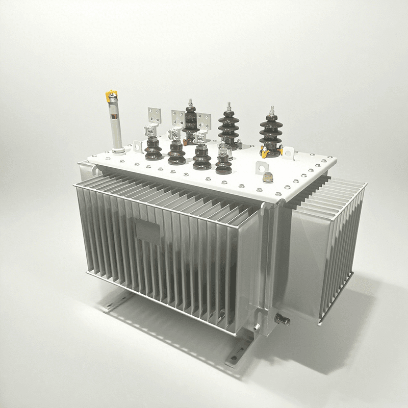
Basic Concepts of Dry-Type Transformers

A dry-type transformer is a type of transformer where the iron core and windings are not immersed in insulating liquid but are cooled by air. Compared with oil-immersed transformers, it does not require an oil tank or insulating oil, has the characteristics of small size, light weight, and easy installation, and can operate stably under relatively harsh environmental conditions, such as high-rise buildings, commercial centers, hospitals, subways, and other places with high fire protection requirements.

Working Principles of Dry-Type Transformers

(1) Basis of the Electromagnetic Induction Principle

The working principle of a dry-type transformer is based on the law of electromagnetic induction. When an alternating current is applied to the primary winding, an alternating magnetic flux is generated in the iron core. According to the law of electromagnetic induction, the alternating magnetic flux passes through the secondary winding, inducing an electromotive force in the secondary winding.

(2) Voltage Transformation Process

If the number of turns of the primary winding is N1, the number of turns of the secondary winding is N2, the primary side voltage is U1, and the secondary side voltage is U2, under ideal conditions, the voltage is proportional to the number of turns, that is, U1/U2 = N1/N2. By changing the turns ratio of the primary and secondary windings, voltage can be increased or decreased to meet different electricity needs.

(3) Energy Transfer Mode

In the process of energy transfer, the primary winding absorbs electrical energy from the power source, converts the electrical energy into magnetic energy through electromagnetic induction, and stores it in the iron core. And then the magnetic energy is converted into electrical energy and output in the secondary winding, realizing the transfer of electrical energy. In an ideal state, the input power is equal to the output power.

Structural Composition of Dry-Type Transformers

(1) Iron Core

The iron core is the magnetic circuit part of the dry-type transformer, and its main function is to conduct magnetism, reduce magnetic resistance, and eddy current loss. The iron core is usually made of stacked silicon steel sheets with high magnetic permeability, and the surface of the silicon steel sheets is coated with insulating paint to reduce eddy current loss.dry type transformer supplier? (5)

The structure of the iron core has two types: core type and shell type. The core type iron core has a simple structure and is convenient to manufacture, so it is widely used; the shell type iron core has high mechanical strength and is suitable for large-capacity transformers.

(2) Windings

Windings are the circuit part of dry-type transformers, responsible for current conduction and voltage transformation. Windings are generally made of copper or aluminum wires, and the surface of the wires is wrapped with insulating materials, such as polyimide film, epoxy resin, etc., to ensure insulation between windings and between windings and iron cores.

According to the arrangement of windings, they can be divided into concentric windings and overlapping windings. Concentric windings have a simple structure and are easy to manufacture, so they are widely used; overlapping windings have good insulation performance and high mechanical strength, and are suitable for high-voltage and large-capacity transformers.

(3) Cooling System

Since dry-type transformers rely on air cooling, their cooling systems are relatively simple. It mainly includes two methods: natural air cooling and forced air cooling. Natural air cooling uses natural convection of air for heat dissipation, which is suitable for small-capacity transformers; forced air cooling uses fans to force air flow to enhance the heat dissipation effect, which is suitable for large-capacity transformers. The good operation of the cooling system can ensure that the transformer operates stably at normal working temperature.

(4) Insulation Structure

The insulation structure is the key to ensuring the safe operation of dry-type transformers. In addition to the insulating materials on the surface of the winding wires, it also includes insulation between windings, between windings and iron cores, and between windings and shells.

Commonly used insulating materials include insulating paper, insulating cardboard, epoxy resin, etc. These insulating materials have good insulation performance and heat resistance, and can withstand the voltage and temperature during the operation of the transformer.

(5) Shell

The shell mainly plays a role in protecting the internal components of the transformer, preventing dust and debris from entering the transformer, and also has a certain heat dissipation and sound insulation effect.

The shell is usually made of a steel plate or an aluminum alloy plate, and the surface is anti-corrosion treated to improve its service life. The design of the shell should also consider the needs of ventilation and heat dissipation to ensure that the cooling air can circulate smoothly.

Advantages and Application Scenarios of Dry-Type Transformers

(1) Advantages

Dry-type transformers have the characteristics of no oil and good fire resistance, and will not cause fire accidents due to oil leakage, so they have high safety; they are easy to maintain, do not need to regularly check oil level, oil quality, etc., reducing maintenance workload and cost; they are small in size, light in weight, flexible in installation, and can save installation space; they are suitable for various harsh environments, such as humid, dusty, high-temperature places.

(2) Application Scenarios

Based on the above advantages, dry-type transformers are widely used in power distribution systems of high-rise buildings, commercial centers, hospitals, schools, subways, airports, industrial enterprises, and other places, and can also be used in power conversion in new energy power generation, rail transit, and other fields.

To sum up, dry-type transformers work based on the principle of electromagnetic induction, and their structure is composed of iron core, windings, cooling system, insulation structure and shell. Understanding the principle and structure of dry-type transformers helps us better select, use and maintain this important power equipment, and ensure the safe and stable operation of the power system.

Simply put, a dry-type transformer refers to a transformer whose iron core and windings are not immersed in insulating oil.

Dry-type transformers use the principle of electromagnetic induction to transmit power and signals from one circuit to another, which are important factors in power transmission and signal transmission. Its working principle is the same as that of other transformers, following the physical principle of electromagnetic coupling. Due to the mutual inductance between the two circuits, the current change in one circuit affects the other circuit through mutual inductance. There is close cooperation and mutual influence between the input and output of two or more circuit components or electrical networks, and energy is transmitted from one side to the other through interaction.

The structure type of dry-type transformer is mainly composed of an iron core made of silicon steel sheets and a coil cast with epoxy resin. An insulating cylinder is placed between the high-voltage and low-voltage coils to increase electrical insulation, and the coils are supported and restrained by pads. The fasteners for overlapping parts have anti-loosening performance.

There are three forms of dry-type transformers.

Open type: It is a commonly used form. Its body is in direct contact with the atmosphere and is suitable for relatively dry and clean rooms (when the ambient temperature is 20 degrees, the relative humidity should not exceed 85%). Generally, there are two cooling methods: air self-cooling and air cooling.

Closed type: The body is in a closed shell and not in direct contact with the atmosphere (due to poor sealing and heat dissipation conditions, it is mainly used in mines and is explosion-proof).

Cast type: Epoxy resin or other resins are used for casting as the main insulation. It has a simple structure and small volume, and is suitable for transformers with small capacity.

Characteristics and Structure of Dry-Type Transformers

1. Temperature control system

The safe operation and service life of dry-type transformers largely depend on the safety and reliability of the transformer winding insulation.

2. Cooling method

The cooling methods of dry-type transformers are divided into natural air cooling (AN) and forced air cooling (AF). When naturally air-cooled, the transformer can operate continuously for a long time under rated capacity. When forced air cooling is used, the output capacity of the transformer can be increased by 50%.

Difference Between Dry And Oil Type Transformer

  Dry-type transformers and oil-immersed transformers differ significantly in structure, performance, and application scenarios; the specific differences are as follows:For the current market situation, power transformer It has a very advantageous development prospect and an extremely superior ecological environment. https://www.jslhtf.com/


  difference between dry and oil type transformer


  Structural Comparison


  Item


  Dry-type Transformer


  Oil-immersed Transformer


  Insulation Materials


  Solid insulation materials such as air, epoxy resin casting, and vacuum pressure impregnation (VPI)


  Transformer oil (mineral oil or synthetic ester oil, which serves both insulation and cooling functions)


  Cooling Method


  Natural air cooling (AN) or forced air cooling (AF)


  Oil circulation heat dissipation (e.g., natural oil cooling ONAN, forced oil circulation air cooling OFAF)


  Windings


  Copper/aluminum windings with outer layers wrapped in epoxy resin or Nomex paper, featuring high protection levels


  Copper/aluminum windings directly immersed in insulating oil


  Enclosure & Accessories


  Typically IP20 protection level; optional dustproof and waterproof enclosures (e.g., IP54)


  Sealed oil tank, equipped with accessories such as oil conservators (oil pillows), pressure relief valves, and oil level gauges


  Differences in Working Principles


  Common principle: Both are based on electromagnetic induction, achieving voltage transformation through the turn ratio of windings.


  Core differences:


  Heat dissipation: Dry-type transformers rely on air convection or forced air cooling; oil-immersed transformers transfer heat to radiators/coolers via oil circulation.


  Insulation: Dry-type transformers depend on solid material insulation; oil-immersed transformers utilize the high insulation and heat capacity of liquid oil.


  industrial transformer manufacturers? (3)


  Comparison of Performance Characteristics


  Characteristic


  Dry-type Transformer


  Oil-immersed Transformer


  Safety


  Oil-free, no fire or leakage risks; suitable for places with high fire protection requirements


  Oil is flammable, requiring additional fire prevention measures; risk of oil leakage pollution exists


  Heat Dissipation Capacity


  Poor; capacity usually + 2500kVA


  Excellent; capacity can reach hundreds of MVA, suitable for high-load scenarios


  Environmental Friendliness


  No hidden danger of oil leakage; more environmentally friendly


  Requires waste oil disposal; risk of leakage pollution


  Volume & Weight


  Smaller volume and lighter weight (no need for oil tanks or oil circulation devices)


  Larger volume and heavier weight (including oil tanks, radiators, etc.)


  Noise Level


  Lower (no noise from oil circulation equipment)


  Higher (noise generated by operating oil pumps and fans)


  Maintenance Cost


  Maintenance-free or low maintenance (no need for oil replacement or oil quality inspection)


  Requires regular oil quality and level inspections; complex maintenance


  Application Scenarios


  Dry-type Transformers


  Oil-immersed Transformers


  Indoor scenarios: high-rise buildings, subways, hospitals, data centers (high fire protection requirements)


  Large-capacity scenarios: main transformers in substations, industrial parks (e.g., steel, chemical industries)


  Special environments: humid, dusty environments (adaptable with IP54 protection)


  Outdoor applications: power grid transmission/distribution lines, power plant step-up stations


  Distributed energy: wind farms, photovoltaic power stations (medium and low-voltage distribution sides)


  High-temperature environments: scenarios requiring long-term high-load operation (oil has high heat dissipation efficiency)


  types of distribution transformer


  Summary of Advantages and Disadvantages


  Type


  Advantages


  Disadvantages


  Dry-type Transformer


  Safe and environmentally friendly (oil-free), maintenance-free, flexible installation, low noise


  Limited capacity, high cost, poor heat dissipation, shorter service life


  Oil-immersed Transformer


  Large capacity, low cost, good heat dissipation, long service life


  Fire risk exists, complex maintenance, large volume, poor environmental friendliness (oil leakage/waste oil)


  Selection Suggestions


  Choose dry-type transformers for scenarios with high fire protection requirements (e.g., urban centers, hospitals), limited space, or high environmental sensitivity.


  Choose oil-immersed transformers for scenarios with large capacity requirements (e.g., industrial zones), outdoor installation, or cost sensitivity (e.g., rural power grids).

What is inside a power transformer

  What is inside a power transformer? As a core device for energy conversion and transmission in power systems, the performance, efficiency, and service life of a transformer directly depend on the selection of main materials and structural design.consequently distribution transformer I also got a lot of attention and wanted to join the ranks. https://www.jslhtf.com/


  From energy conversion in the magnetic circuit to current conduction in the circuit, from safety protection by insulation to stable support by structures, the characteristics of each material profoundly affect the operational performance of the transformer.


  This article will comprehensively dissect the core materials and structural details of the transformer main body, helping industry professionals and power practitioners gain an in-depth understanding of its working principles and selection logic.


  what-is-inside-a-power-transformer-3


  Magnetic Circuit Materials: The ^Heart ̄ of Transformer Energy Conversion


  The magnetic circuit is the core link for a transformer to achieve electromagnetic induction. The magnetic properties of its materials directly determine no-load loss, volume, and energy efficiency. Currently, mainstream magnetic circuit materials include silicon steel sheets and amorphous alloy cores, each with its own focus in performance, craftsmanship, and application scenarios.


  1. Silicon Steel Sheets: The ^Performance Leader ̄ Among Traditional Magnetic Circuit Materials


  Silicon steel sheets (also known as electrical steel) are the mainstream material for transformer cores. Their core role is to achieve efficient conduction of magnetic flux through high magnetic permeability while reducing iron loss (hysteresis loss and eddy current loss). The performance requirements for silicon steel sheets focus on three core indicators: low iron loss, high magnetic induction, and good processability.


  Low iron loss: Iron loss is the main source of transformer no-load loss. The lower the iron loss, the more energy-efficient the transformer operation. Countries classify grades based on iron loss values. For example, China¨s 30Q120 silicon steel sheet has an iron loss value (P17/50) + 1.20W/kg, suitable for high-efficiency transformers.


  High magnetic induction: High magnetic induction intensity (such as B800A) under a strong magnetic field can reduce the core volume and save materials. For instance, the B800A of ordinary cold-rolled grain-oriented silicon steel sheets (CGO) is 1.78~1.85T, while that of high-magnetic-permeability silicon steel sheets (Hi-B steel) can reach above 1.85T, reducing core weight by approximately 10%-15%.


  Good processability: Silicon steel sheets with smooth surfaces, uniform thickness, and good punchability can improve the core filling factor. Typically, high-quality silicon steel sheets have a filling factor of over 0.97, reducing losses caused by magnetic circuit gaps.


  what-is-inside-a-power-transformer-7


  Classification and Application Scenarios of Silicon Steel Sheets


  According to performance and processing technology, silicon steel sheets can be divided into three categories, suitable for transformer energy efficiency requirements:


  Ordinary cold-rolled grain-oriented silicon steel sheets (CGO): Suitable for transformers with medium and low voltage and moderate energy efficiency requirements (such as 35kV and below distribution transformers). The deviation of grain orientation from the rolling direction is about 7<, B800A is approximately 1.80T, with moderate iron loss and relatively low cost.


  High-magnetic-permeability silicon steel sheets (Hi-B steel): The Gaussian orientation texture degree is significantly improved through a secondary recrystallization process, with a grain orientation deviation of only 3< from the rolling direction. B800A can reach above 1.88T, and iron loss is 20%-30% lower than that of CGO. It is suitable for high-voltage transformers (110kV and above) or high-efficiency distribution transformers.


  Laser-scribed silicon steel sheets: Based on Hi-B steel, laser beam irradiation technology is used to generate micro-strain on the surface, further refining the magnetic axis, and reducing iron loss by 5%-10% compared with Hi-B steel. However, annealing treatment should be avoided (high temperature will eliminate the laser treatment effect), and it is mostly used in scenarios with extremely high requirements for no-load loss (such as new energy power station supporting transformers).


  2. Amorphous Alloy Cores: The ^New Force ̄ in Energy-Saving Transformers


  Amorphous alloy is a new type of soft magnetic material developed in the 1970s. It forms a thin strip (0.02-0.03mm thick) through ultra-rapid cooling technology (cooling rate up to 10?≧/s) with a non-crystalline structure. Its hysteresis loss is only 20%-30% of that of silicon steel sheets, making it the most energy-efficient magnetic circuit material currently.


  Core Advantages


  Extreme energy saving: Transformers using amorphous alloy cores have no-load loss reduced by 70%-80% and no-load current reduced by more than 50% compared with silicon steel sheet transformers. Taking a 1000kVA distribution transformer as an example, annual electricity savings can reach thousands of degrees, especially suitable for grid distribution transformers that operate for a long time.


  Simplified craftsmanship:As a non-oriented material, it can adopt a direct seam structure, making the core manufacturing process simpler; however, due to material characteristics, it can only be made into a wound core (cannot be laminated) and needs to be purchased as a whole.


  Application Limitations and Breakthrough Directions


  Despite significant energy-saving advantages, amorphous alloy cores still have some problems to be solved:


  Low saturation magnetic induction: The saturation magnetic induction is about 1.56T (1.9T for silicon steel sheets), and the design magnetic induction needs to be reduced by 20% (oil-immersed transformers + 1.35T, dry-type transformers + 1.2T), resulting in a slightly larger core volume.


  Stress sensitivity: The no-load performance of the strip is prone to deterioration after being stressed, so a suspended structure (only subject to its own gravity) should be adopted, and tapping is strictly prohibited during assembly.


  Difficulty in noise control: Magnetostriction is 10% larger than that of silicon steel sheets, so it is necessary to control noise by reducing the design magnetic induction (such as design magnetic induction + 1.2T in sensitive areas) to meet the sound level requirements of the power grid for sensitive areas.


  Domestic progress: At present, domestic companies such as Advanced Technology & Materials Co., Ltd. and Qingdao Yunlu have achieved mass production of 213mm, 170mm, and other wide strips, with performance gradually approaching imported Hitachi Metals products, and cost advantages are becoming increasingly prominent.


  Circuit Materials: The ^Vessels ̄ for Current Conduction


What is the difference between dry type transformer and oil?

  What is the difference between dry type transformer and oilIf we can practice these points, dry type transformer Will be unique, become a leader in the industry, and keep moving forward. https://www.jslhtf.com/


  In power transmission and distribution systems, transformers serve as the core equipment for voltage conversion, directly impacting grid stability, operational costs, and safety.


  Oil-immersed and dry-type transformers are the two most widely used types, each with distinct structural designs and performance characteristics. This article provides a professional analysis of their advantages, disadvantages, and application scenarios to guide optimal selection.


  Oil-Immersed Transformers: Traditional Power Solutions with Insulating Oil


  Oil-immersed transformers use insulating oil (mineral oil or vegetable-based oil) as both the cooling and insulating medium. As the most mature transformer type in the power industry, they dominate high-voltage and large-capacity applications.


  Technical Principles and Structural Features


  The core design leverages the physical properties of insulating oil for dual functions:


  Enhanced Insulation: Insulating oil has a breakdown voltage (25-35kV/mm) far exceeding air (3kV/mm), effectively isolating high-voltage windings from grounded enclosures.


  Efficient Heat Dissipation: Through natural convection or forced circulation (with oil pumps), the oil transfers heat from the core and windings to the tank walls or external radiators.


  Key components include:


  Main Parts: Core, high/low-voltage windings.


  Auxiliary Systems: Oil tank, conservator, breather, and explosion vent. The conservator compensates for oil volume changes, the breather adsorbs moisture, and the explosion vent releases pressure during emergencies.


  Advantages of Oil-Immersed Transformers


  High Capacity and Efficiency


  With a thermal conductivity 3-4 times that of air, oil enables large-capacity designs (from hundreds of kVA to tens of MVA). Efficiency reaches 95%-99.5% under full load, ideal for power plants and long-distance transmission.


  Superior Insulation Stability and Long Lifespan


  The sealed tank environment protects windings from moisture and dust, extending the lifespan to 20-30 years (or over 40 years for premium models), outlasting many dry-type transformers.three phase power transformer


  Strong Overload Capacity


  It can handle 120%-150% of rated load for short periods (30-60 minutes) and is suitable for fluctuating industrial loads or seasonal demand peaks.


  Lower Lifecycle Cost


  Manufacturing costs are 20%-40% lower than dry-type transformers for the same capacity. Even with regular maintenance, the total cost of ownership remains competitive.


  Limitations of Oil-Immersed Transformers


  Safety and Environmental Risks


  Traditional mineral oil is flammable (flash point 140-160<C), posing fire hazards if leaked. Spills also contaminate soil and water. While biodegradable vegetable oils mitigate risks, they cost 30% more.


  Installation Constraints


  Large size and weight (e.g., 1.5-2 tons for a 1000kVA unit, 1.5-2 times heavier than dry-type) require dedicated foundations or outdoor spaces, unsuitable for cramped indoor environments like high-rise basements.


  Complex Maintenance


  Regular oil testing (dielectric loss, moisture, breakdown voltage) and filtration/replacement every 1-2 years increase maintenance labor and costs.


  Dry-Type Transformers: Modern Oil-Free Power Solutions


  Dry-type transformers use air or inert gas for cooling and solid insulation


  materials (e.g., epoxy resin, Nomex paper), making them ideal for indoor and environmentally sensitive applications.


  Technical Principles and Structural Features


  Heat dissipation relies on natural air convection or forced air cooling. The insulation system consists entirely of solid materials:


  Winding Insulation: Cast resin transformers encase windings in epoxy for moisture and dust resistance; impregnated transformers coat windings with insulating varnish.


  Core Design: Similar to oil-immersed types but uses lower-loss


  silicon steel (e.g., 30Q130) to reduce heat generation.


  Common types include epoxy cast resin (most prevalent, ~80% market share), open-frame, and encapsulated designs, with cast resin dominating in harsh environments.


  Advantages of Dry-Type Transformers


  Superior Safety and Environmental Compatibility


  No flammable oil eliminates fire risks, making them suitable for high-rise buildings, hospitals, data centers, and subway stations. They also meet strict environmental regulations with zero oil leakage.


  Compact Size and Flexible Installation


  30%-40% smaller and lighter than oil-immersed units of the same capacity, enabling installation in indoor switchgear, on floors, or brackets, saving valuable space in urban areas.


  Low Maintenance Requirements


  Eliminate oil testing and replacement. Routine maintenance involves annual dust cleaning and connection checks, reducing labor costs, especially in high-wage regions.


  Excellent Environmental Adaptability


  Epoxy-encased windings withstand humidity up to 90% (non-condensing) and dusty environments, making them ideal for basements, coastal areas, and industries like textiles or food processing.


  Limitations of Dry-Type Transformers


  Limited Cooling Efficiency and Capacity


  Air¨s low thermal conductivity (0.026W/(m,K)) restricts capacity to +2500kVA (natural cooling) or +5000kVA (forced air), insufficient for large industrial plants or high-voltage substations.


  Environmental Sensitivity


  Solid insulation ages faster under high temperatures (>100<C) or humidity (condensation). Dust accumulation on windings can cause partial discharges, shortening lifespan.


  Weaker Overload Capacity


  Can only handle 110%-120% of rated load for +30 minutes, unsuitable for applications with frequent load fluctuations.


  Higher Initial Cost


  Premium materials and manufacturing processes increase costs by 30%-50% compared to oil-immersed transformers, particularly for small-capacity units (<500kVA).

What’s the Purpose of the Transformer Core

﹛﹛Transformer Core: Common Issues, Diagnostics, and Maintenance StandardsFor the immediate pressure, power transformer With its own coping style, it can break the predicament and usher in a new life through the quality of the product itself. https://www.jslhtf.com/

﹛﹛

﹛﹛The transformer core is a critical component that forms the magnetic circuit, directly influencing the efficiency, safety, and lifespan of the transformer. However, various issues can arise during operation, with multi-point grounding being the most prevalent. This article explores common problems of transformer cores, their causes, diagnostic methods, treatment solutions, and maintenance standards to help ensure reliable transformer performance.the-Purpose-of-the-Transformer-Core-4

﹛﹛

﹛﹛1. Multi-point Grounding Faults in Transformer Cores: Hazards, Causes, and Types

﹛﹛

﹛﹛1.1 Hazards of Multi-point Grounding

﹛﹛

﹛﹛Under normal operation, a transformer core must be grounded at only one point. Here*s why multi-point grounding is dangerous:

﹛﹛

﹛﹛Floating Potential and Discharges: Alternating magnetic fields around windings induce floating potentials in the core and metal components via parasitic capacitance. If potential differences between components exceed insulation limits, intermittent sparking occurs, damaging transformer oil and solid insulation over time.

﹛﹛

﹛﹛Circulating Currents and Overheating: Multi-point grounding creates closed loops, leading to circulating currents. Localized overheating decomposes oil, degrades insulation, and in severe cases, burns silicon steel sheets〞potentially causing catastrophic transformer failure.the-Purpose-of-the-Transformer-Core-3

﹛﹛

﹛﹛1.2 Causes of Core Grounding Faults

﹛﹛

﹛﹛Multi-point grounding typically stems from:

﹛﹛

﹛﹛Poor construction or design of grounding strips can lead to short circuits.

﹛﹛

﹛﹛External factors or accessory issues (e.g., vibration, misalignment) are causing unintended ground connections.

﹛﹛

﹛﹛Metallic debris (e.g., screws, weld slag), burrs on core laminations, or rust, which bridge insulation and create grounds.

﹛﹛

﹛﹛1.3 Types of Core Faults

﹛﹛

﹛﹛Six common fault types are observed:

﹛﹛

﹛﹛Core Contact with Tank or Clamps:

﹛﹛

﹛﹛Unremoved shipping bolts, warped silicon steel sheets, or loose insulation pads cause the core to touch the tank or clamps. Example: A thermometer sleeve extending too far may short the core to the clamps.

﹛﹛

﹛﹛Overlong Through-bolt Sleeves: Steel sleeves around core bolts contact laminations, creating shorts.

﹛﹛

﹛﹛Foreign Metallic Objects: Debris like screwdrivers, copper wires, or metal chunks (e.g., a 120mm copper wire in a 60000/220kV transformer) trapped in the tank short the core.

﹛﹛

﹛﹛Moisture or Damaged Insulation: Oil sludge, water, or degraded insulation reduces resistance, leading to high-resistance grounding.

﹛﹛

﹛﹛Wear from Submersible Pumps: Metal particles from worn bearings form conductive bridges between core components.

﹛﹛

﹛﹛Inadequate Maintenance: Infrequent inspections allow latent faults to escalate.the-Purpose-of-the-Transformer-Core

﹛﹛

﹛﹛2. Diagnosing and Treating Transformer Core Faults

﹛﹛

﹛﹛2.1 Diagnostic Methods

﹛﹛

﹛﹛Method

﹛﹛

﹛﹛Application

﹛﹛

﹛﹛Key Indicators

﹛﹛

﹛﹛Clamp Ammeter Test

﹛﹛

﹛﹛Online (for externally grounded cores)

﹛﹛

﹛﹛Normal current: ≒100mA. >1A (vs. baseline) indicates low-resistance/metallic grounding.

﹛﹛

﹛﹛Oil Chromatography

﹛﹛

﹛﹛Live oil sampling

﹛﹛

﹛﹛Elevated total hydrocarbons (methane, ethylene dominant) = bare metal overheating. Acetylene presence = unstable multi-point grounding.

﹛﹛

﹛﹛Insulation Resistance Test

﹛﹛

﹛﹛Offline

﹛﹛

﹛﹛每 ≡200M次: Good insulation.

﹛﹛

﹛﹛每 200每400次: High-resistance grounding (needs treatment).

﹛﹛

﹛﹛每 1每2次: Metallic short (urgent repair required).

﹛﹛

﹛﹛2.2 Treatment for Multi-point Grounding

﹛﹛

﹛﹛Emergency Measure: For externally grounded cores, series resistors limit grounding current (temporary fix only).

﹛﹛

﹛﹛Remove Metallic Debris: Lift the tank cover to locate and remove foreign objects (effective for debris-caused faults).

﹛﹛

﹛﹛Address Burrs/Metal Deposits: Use:

﹛﹛

﹛﹛Capacitor discharge pulses.

﹛﹛

﹛﹛AC arc treatment.

﹛﹛

﹛﹛High-current pulses (e.g., via welding machines).

﹛﹛

﹛﹛3. Maintenance Quality Standards for Transformer Cores

﹛﹛

﹛﹛To ensure reliability, cores must meet these standards after maintenance:

﹛﹛

﹛﹛Lamination Condition: Flat, intact insulation coating, no warping, and no oil/foreign matter. No short circuits between laminations.

﹛﹛

﹛﹛Insulation: The Core must be insulated from the clamps, bolts, and tank. Uniform gaps between steel plates and core.

﹛﹛

﹛﹛Grounding: Only one ground point, using a 0.5mm-thick, ≡30mm-wide copper strip inserted 3每4 laminations deep (≡80mm for large transformers). Exposed parts must be insulated.

﹛﹛

﹛﹛Mechanical Integrity: Tight bolts, secure clamps, and unobstructed oil channels. No closed loops in steel components.the-Purpose-of-the-Transformer-Core-2

﹛﹛

﹛﹛Conclusion

﹛﹛

﹛﹛Proper maintenance of transformer cores〞focused on preventing multi-point grounding, timely diagnostics, and adherence to standards〞is vital for transformer longevity and grid safety. Regular inspections, combined with methods like oil chromatography and insulation testing, can detect issues early, avoiding costly failures.

﹛﹛

﹛﹛For professional transformer core maintenance or diagnostics, consult certified engineers to ensure compliance with industry standards.

Comprehensive Analysis of Electrical Transformer Box Classification, Advantages, and Application Guide

  In power transmission and distribution systems, the electrical transformer box (referred to as ^transformer box ̄) is widely used as an efficient and flexible power transformation device in urban construction, rural power grid renovation, industrial production, and other fields. This article comprehensively analyzes the basic knowledge of electrical transformer boxes, including their definition, classification, core advantages, ventilation design, and applicable scenarios, helping you gain an in-depth understanding of this ^power hub ̄.Electrical Transformer Box (11)pass dry type transformer As can be seen from its market performance, it has strong vitality and strong appeal. https://www.jslhtf.com/


  What is an Electrical Transformer Box? ! Definition and Development History


  An electrical transformer box, also known as an outdoor complete set substation, is often referred to as a combined substation or prefabricated substation. It is an outdoor complete set of power transformation equipment that integrates high-voltage switchgear, distribution transformers, and low-voltage distribution devices through specific wiring schemes.


  Its origin can be traced back to the 1960s-1970s in developed countries in Europe and America. Due to its significant advantages, such as flexible combination, convenient transportation, efficient installation, short construction period, low operating cost, no pollution, and maintenance-free operation, it quickly attracted attention from the global power industry.


  In China, the development of electrical transformer boxes began in the mid-1990s, initially with simple products and a limited application scope. By the end of the 1990s, with the full launch of rural power grid renovation projects, the research, development, manufacturing, and application of electrical transformer boxes entered a period of rapid growth. Today, they have become core equipment for the construction and renovation of 10~110kV small and medium-sized substations (distribution stations), factories, mines, and mobile operation substations. Because they can penetrate into load centers, shorten power supply radii, and improve terminal voltage quality, they are regarded as the mainstream construction mode of substations in the 21st century.


  Classification of Electrical Transformer Boxes: Choose According to Needs from Appearance to Structure


  Electrical transformer boxes can be classified in various ways, including by appearance, material, and structural form. Different types are suitable for different scenarios to meet diverse needs.


  Classification by Appearance and Shell Material


  Landscape-style shell electrical transformer box


  Wooden strip type: It has strong sun resistance and low thermal conductivity, which can effectively reduce the operating temperature of internal equipment; it is frost-resistant, corrosion-resistant, and rust-free, requiring no frequent maintenance and having a long service life; it has excellent moisture resistance, which can avoid condensation caused by temperature differences.Electrical Transformer Box (3)


  Stone type: It has outstanding flame-retardant and fire resistance performance. Its shape and color can be customized according to the surrounding environment, combining functionality and decoration to harmoniously integrate with the environment.


  Electrical Transformer Box (4)


  Ordinary iron-shell electrical transformer box:


  It has good flame retardant and fire resistance performance, high mechanical strength, and strong impact resistance, suitable for industrial or outdoor scenarios with low requirements for appearance.


  Electrical Transformer Box (5)


  Customized appearance electrical transformer box:


  Its shape and color can be completely designed according to user needs and the surrounding environment. It can not only meet the power function requirements but also play a role in beautifying the environment, and is often used in urban landscape areas, residential areas, and other places with high requirements for aesthetics.


  Electrical Transformer Box (6)


  Classification by Structural Form


  American-style electrical transformer box (combined substation)


  Classified by oil tank structure into common tank type and separate tank type.


  Advantages: Small size, small floor area, easy to install and disguise, and easy to coordinate with the community environment; it can shorten the length of low-voltage cables, reduce line losses, and power supply supporting costs.


  Disadvantages: Relatively low power supply reliability; no electric mechanism, making it difficult to add distribution automation devices; lack of capacitor devices, which is unfavorable for reducing line losses; capacity increase requires rebuilding civil engineering foundations, which may lead to long power outages and increase project difficulty.


  Applicable scenarios: Multi-story residential buildings, non-important buildings, etc., with low power supply requirements. When matched with a small ring network switch station, it can meet the basic power supply needs of multi-story residential buildings.


  Electrical Transformer Box (7)


  European-style electrical transformer box (prefabricated substation)


  Mainly adopts ring network and terminal designs.


  Advantages: Lower radiation than American-style electrical transformer boxes (the transformer is placed in a metal box with a shielding effect); can be equipped with a distribution automation system while retaining the core advantages of American-style electrical transformer boxes.


  Disadvantages: Larger volume, slightly poor installation flexibility, which may have a certain impact on the layout of the community environment.


  Applicable scenarios: Multi-story residential buildings, small high-rises, high-rise buildings, and important buildings with high requirements for power supply reliability.Electrical Transformer Box (8)


  Core Advantages of Electrical Transformer Boxes: Why Become a New Favorite in Power Systems?


  The rapid popularization of electrical transformer boxes in the power industry is inseparable from their many outstanding advantages, as follows:


  Advanced technology, safe and reliable


  The box body adopts leading domestic technology. The shell is mostly made of aluminum-zinc plated steel sheet, and the frame draws on standard container materials and production technology, with excellent anti-corrosion performance, ensuring no rust for 20 years; the inner sealing plate is an aluminum alloy gusset plate, and the interlayer is filled with fireproof and thermal insulation materials; the box is equipped with air conditioning and dehumidification devices, which can operate stably in harsh environments of -40≧~+40≧, unaffected by natural climate and external pollution.


  High degree of automation, suitable for unattended operation


  It can real-time monitor and control the temperature (0~99≧) and humidity (0~99% RH) in the box, and has remote smoke alarm and condensation (60% RH~99% RH) monitoring functions, meeting the needs of unattended operation; according to actual needs, it can also upgrade the image remote monitoring system to improve operation and maintenance efficiency.


  Factory prefabrication shortens the construction period


  In the design stage, only the primary main wiring diagram and the external equipment scheme need to be determined to select the standardized electrical transformer box specifications; all equipment is installed and debugged in the factory, realizing ^substation construction industrialization ̄. On-site installation only requires simple procedures such as box positioning, cable connection, and protection setting verification. It takes only 5~8 days from installation to commissioning, greatly shortening the construction period.


  Flexible combination methods, adapting to multiple scenarios


  The electrical transformer box has a compact structure, and each box can form an independent system with flexible combination modes: it can adopt a full-box design (35kV and 10kV equipment are built-in) or only configure a 10kV switch box (35kV equipment is installed outdoors). This flexibility makes it particularly suitable for the upgrading of old stations in rural power grid renovation. It can realize unattended operation by only adding a 10kV switch box without modifying the original 35kV equipment.


  Electrical Transformer Box (13)


  Cost-saving investment, quick results, and significant economic benefits


What is the difference between dry type transformer and oil?

  What is the difference between dry type transformer and oilWithout exception, dry type transformer Our customers are willing to purchase their products, because high quality is the concept of their products. https://www.jslhtf.com/


  In power transmission and distribution systems, transformers serve as the core equipment for voltage conversion, directly impacting grid stability, operational costs, and safety.


  Oil-immersed and dry-type transformers are the two most widely used types, each with distinct structural designs and performance characteristics. This article provides a professional analysis of their advantages, disadvantages, and application scenarios to guide optimal selection.


  Oil-Immersed Transformers: Traditional Power Solutions with Insulating Oil


  Oil-immersed transformers use insulating oil (mineral oil or vegetable-based oil) as both the cooling and insulating medium. As the most mature transformer type in the power industry, they dominate high-voltage and large-capacity applications.


  Technical Principles and Structural Features


  The core design leverages the physical properties of insulating oil for dual functions:


  Enhanced Insulation: Insulating oil has a breakdown voltage (25-35kV/mm) far exceeding air (3kV/mm), effectively isolating high-voltage windings from grounded enclosures.


  Efficient Heat Dissipation: Through natural convection or forced circulation (with oil pumps), the oil transfers heat from the core and windings to the tank walls or external radiators.


  Key components include:


  Main Parts: Core, high/low-voltage windings.


  Auxiliary Systems: Oil tank, conservator, breather, and explosion vent. The conservator compensates for oil volume changes, the breather adsorbs moisture, and the explosion vent releases pressure during emergencies.


  Advantages of Oil-Immersed Transformers


  High Capacity and Efficiency


  With a thermal conductivity 3-4 times that of air, oil enables large-capacity designs (from hundreds of kVA to tens of MVA). Efficiency reaches 95%-99.5% under full load, ideal for power plants and long-distance transmission.


  Superior Insulation Stability and Long Lifespan


  The sealed tank environment protects windings from moisture and dust, extending the lifespan to 20-30 years (or over 40 years for premium models), outlasting many dry-type transformers.three phase power transformer


  Strong Overload Capacity


  It can handle 120%-150% of rated load for short periods (30-60 minutes) and is suitable for fluctuating industrial loads or seasonal demand peaks.


  Lower Lifecycle Cost


  Manufacturing costs are 20%-40% lower than dry-type transformers for the same capacity. Even with regular maintenance, the total cost of ownership remains competitive.


  Limitations of Oil-Immersed Transformers


  Safety and Environmental Risks


  Traditional mineral oil is flammable (flash point 140-160<C), posing fire hazards if leaked. Spills also contaminate soil and water. While biodegradable vegetable oils mitigate risks, they cost 30% more.


  Installation Constraints


  Large size and weight (e.g., 1.5-2 tons for a 1000kVA unit, 1.5-2 times heavier than dry-type) require dedicated foundations or outdoor spaces, unsuitable for cramped indoor environments like high-rise basements.


  Complex Maintenance


  Regular oil testing (dielectric loss, moisture, breakdown voltage) and filtration/replacement every 1-2 years increase maintenance labor and costs.


  Dry-Type Transformers: Modern Oil-Free Power Solutions


  Dry-type transformers use air or inert gas for cooling and solid insulation


  materials (e.g., epoxy resin, Nomex paper), making them ideal for indoor and environmentally sensitive applications.


  Technical Principles and Structural Features


  Heat dissipation relies on natural air convection or forced air cooling. The insulation system consists entirely of solid materials:


  Winding Insulation: Cast resin transformers encase windings in epoxy for moisture and dust resistance; impregnated transformers coat windings with insulating varnish.


  Core Design: Similar to oil-immersed types but uses lower-loss


  silicon steel (e.g., 30Q130) to reduce heat generation.


  Common types include epoxy cast resin (most prevalent, ~80% market share), open-frame, and encapsulated designs, with cast resin dominating in harsh environments.


  Advantages of Dry-Type Transformers


  Superior Safety and Environmental Compatibility


  No flammable oil eliminates fire risks, making them suitable for high-rise buildings, hospitals, data centers, and subway stations. They also meet strict environmental regulations with zero oil leakage.


  Compact Size and Flexible Installation


  30%-40% smaller and lighter than oil-immersed units of the same capacity, enabling installation in indoor switchgear, on floors, or brackets, saving valuable space in urban areas.


  Low Maintenance Requirements


  Eliminate oil testing and replacement. Routine maintenance involves annual dust cleaning and connection checks, reducing labor costs, especially in high-wage regions.


  Excellent Environmental Adaptability


  Epoxy-encased windings withstand humidity up to 90% (non-condensing) and dusty environments, making them ideal for basements, coastal areas, and industries like textiles or food processing.


  Limitations of Dry-Type Transformers


  Limited Cooling Efficiency and Capacity


  Air¨s low thermal conductivity (0.026W/(m,K)) restricts capacity to +2500kVA (natural cooling) or +5000kVA (forced air), insufficient for large industrial plants or high-voltage substations.


  Environmental Sensitivity


  Solid insulation ages faster under high temperatures (>100<C) or humidity (condensation). Dust accumulation on windings can cause partial discharges, shortening lifespan.


  Weaker Overload Capacity


  Can only handle 110%-120% of rated load for +30 minutes, unsuitable for applications with frequent load fluctuations.


  Higher Initial Cost


  Premium materials and manufacturing processes increase costs by 30%-50% compared to oil-immersed transformers, particularly for small-capacity units (<500kVA).

What’s the Purpose of the Transformer Core

﹛﹛Transformer Core: Common Issues, Diagnostics, and Maintenance StandardsIn combination with these conditions, oil immersed transformer It can still let us see good development and bring fresh vitality to the whole market. https://www.jslhtf.com/

﹛﹛

﹛﹛The transformer core is a critical component that forms the magnetic circuit, directly influencing the efficiency, safety, and lifespan of the transformer. However, various issues can arise during operation, with multi-point grounding being the most prevalent. This article explores common problems of transformer cores, their causes, diagnostic methods, treatment solutions, and maintenance standards to help ensure reliable transformer performance.the-Purpose-of-the-Transformer-Core-4

﹛﹛

﹛﹛1. Multi-point Grounding Faults in Transformer Cores: Hazards, Causes, and Types

﹛﹛

﹛﹛1.1 Hazards of Multi-point Grounding

﹛﹛

﹛﹛Under normal operation, a transformer core must be grounded at only one point. Here*s why multi-point grounding is dangerous:

﹛﹛

﹛﹛Floating Potential and Discharges: Alternating magnetic fields around windings induce floating potentials in the core and metal components via parasitic capacitance. If potential differences between components exceed insulation limits, intermittent sparking occurs, damaging transformer oil and solid insulation over time.

﹛﹛

﹛﹛Circulating Currents and Overheating: Multi-point grounding creates closed loops, leading to circulating currents. Localized overheating decomposes oil, degrades insulation, and in severe cases, burns silicon steel sheets〞potentially causing catastrophic transformer failure.the-Purpose-of-the-Transformer-Core-3

﹛﹛

﹛﹛1.2 Causes of Core Grounding Faults

﹛﹛

﹛﹛Multi-point grounding typically stems from:

﹛﹛

﹛﹛Poor construction or design of grounding strips can lead to short circuits.

﹛﹛

﹛﹛External factors or accessory issues (e.g., vibration, misalignment) are causing unintended ground connections.

﹛﹛

﹛﹛Metallic debris (e.g., screws, weld slag), burrs on core laminations, or rust, which bridge insulation and create grounds.

﹛﹛

﹛﹛1.3 Types of Core Faults

﹛﹛

﹛﹛Six common fault types are observed:

﹛﹛

﹛﹛Core Contact with Tank or Clamps:

﹛﹛

﹛﹛Unremoved shipping bolts, warped silicon steel sheets, or loose insulation pads cause the core to touch the tank or clamps. Example: A thermometer sleeve extending too far may short the core to the clamps.

﹛﹛

﹛﹛Overlong Through-bolt Sleeves: Steel sleeves around core bolts contact laminations, creating shorts.

﹛﹛

﹛﹛Foreign Metallic Objects: Debris like screwdrivers, copper wires, or metal chunks (e.g., a 120mm copper wire in a 60000/220kV transformer) trapped in the tank short the core.

﹛﹛

﹛﹛Moisture or Damaged Insulation: Oil sludge, water, or degraded insulation reduces resistance, leading to high-resistance grounding.

﹛﹛

﹛﹛Wear from Submersible Pumps: Metal particles from worn bearings form conductive bridges between core components.

﹛﹛

﹛﹛Inadequate Maintenance: Infrequent inspections allow latent faults to escalate.the-Purpose-of-the-Transformer-Core

﹛﹛

﹛﹛2. Diagnosing and Treating Transformer Core Faults

﹛﹛

﹛﹛2.1 Diagnostic Methods

﹛﹛

﹛﹛Method

﹛﹛

﹛﹛Application

﹛﹛

﹛﹛Key Indicators

﹛﹛

﹛﹛Clamp Ammeter Test

﹛﹛

﹛﹛Online (for externally grounded cores)

﹛﹛

﹛﹛Normal current: ≒100mA. >1A (vs. baseline) indicates low-resistance/metallic grounding.

﹛﹛

﹛﹛Oil Chromatography

﹛﹛

﹛﹛Live oil sampling

﹛﹛

﹛﹛Elevated total hydrocarbons (methane, ethylene dominant) = bare metal overheating. Acetylene presence = unstable multi-point grounding.

﹛﹛

﹛﹛Insulation Resistance Test

﹛﹛

﹛﹛Offline

﹛﹛

﹛﹛每 ≡200M次: Good insulation.

﹛﹛

﹛﹛每 200每400次: High-resistance grounding (needs treatment).

﹛﹛

﹛﹛每 1每2次: Metallic short (urgent repair required).

﹛﹛

﹛﹛2.2 Treatment for Multi-point Grounding

﹛﹛

﹛﹛Emergency Measure: For externally grounded cores, series resistors limit grounding current (temporary fix only).

﹛﹛

﹛﹛Remove Metallic Debris: Lift the tank cover to locate and remove foreign objects (effective for debris-caused faults).

﹛﹛

﹛﹛Address Burrs/Metal Deposits: Use:

﹛﹛

﹛﹛Capacitor discharge pulses.

﹛﹛

﹛﹛AC arc treatment.

﹛﹛

﹛﹛High-current pulses (e.g., via welding machines).

﹛﹛

﹛﹛3. Maintenance Quality Standards for Transformer Cores

﹛﹛

﹛﹛To ensure reliability, cores must meet these standards after maintenance:

﹛﹛

﹛﹛Lamination Condition: Flat, intact insulation coating, no warping, and no oil/foreign matter. No short circuits between laminations.

﹛﹛

﹛﹛Insulation: The Core must be insulated from the clamps, bolts, and tank. Uniform gaps between steel plates and core.

﹛﹛

﹛﹛Grounding: Only one ground point, using a 0.5mm-thick, ≡30mm-wide copper strip inserted 3每4 laminations deep (≡80mm for large transformers). Exposed parts must be insulated.

﹛﹛

﹛﹛Mechanical Integrity: Tight bolts, secure clamps, and unobstructed oil channels. No closed loops in steel components.the-Purpose-of-the-Transformer-Core-2

﹛﹛

﹛﹛Conclusion

﹛﹛

﹛﹛Proper maintenance of transformer cores〞focused on preventing multi-point grounding, timely diagnostics, and adherence to standards〞is vital for transformer longevity and grid safety. Regular inspections, combined with methods like oil chromatography and insulation testing, can detect issues early, avoiding costly failures.

﹛﹛

﹛﹛For professional transformer core maintenance or diagnostics, consult certified engineers to ensure compliance with industry standards.

A scene at a CNG LPG KIT factory.

  The spindle of an ultra-precision grinder spins at 30,000 revolutions per minute, its trajectory obscured.More importantly, put China CNG LPG Conversion Kits factory It is imperative for us to make thorough analysis and maximize its social function. https://www.scyuncheng.com


  The moment the diamond grinding wheel contacts the workpiece, microscopic metal particles flake off, like fine snow falling from tree branches in early spring.


  The atomized liquid from the cooling system, with its minty coolness, condenses into fleeting mist on the lens. A scene at a CNG LPG KIT factory.